In order to measure the THD of tube amplifiers (adjusting Bias, cathode resistors etc.) I needed a simple notchfilter that can measure THD down to approx. 0,01% U. My generator is an old LEVELL that should be better than 0,05%, good enough for these mesurements of tube circuits.
because I wanted to tune automatically, I used a circuit that is not critical for parts value's. The meter was designed and build in a few days and does not pretend to be an instrument to measure down to unbelievable low value's, it is just a practical tool for the design of my amps.
The THD meter is finished and works as expected. I use 700 Hz in order to have all components and expected harmonics well in the audio band.
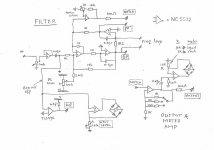
First of all, the diagram
The input goes via a 500K pot to an opamp in order to have a high input impedance. The input level should be adjusted to 200 mV eff, a meter circuit is included wich should be calibrated . Screem the input from the meter circuit, the signal at the meter may introduce some capacitively coupled distorsion into the input. The input to the filter is also led to a comparator in order to have a reference signal for the nulling loops.
The filter is a variable state filter connected such that there is little dependence of component value's. Normal E12 resistors and caps can be used. The filter has a notch output (via an amplifier), a band pass output (BP) and a 90-degrees output, used in the nulling loops.
When build as such, the filter will give you approx a notch with a factor 50 - 100 attenuation, wich is not sufficient for most THD measurements.
But the Notch output is in counter phase with the BP output, so when a small amount of BP signal is added to the NOTCH output, one can get a very deep null. But the frequency becomes extremely sharp ( a part of a Hz) and tuning becomes almost impossible.
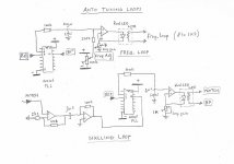
Therefore, I added a control loop for the frequency by adjusting the drive resistor of the second integrator with a LDR driven by a red LED. Both are mounted together in a piece of shrink sleeve. The tuning information comes from the phase of the REF signal and the 90 degrees signal. These are 90 degrees out of phase when tuned correctly. I used the pahse comparator 1 of CD4046 PLL circuits for simplicity
In order to test, first test the filter without the LDR for the frequency loop and the nulling loop connected. One should get a Notch at approx 6500 Hz. Set the DC NULL so that there is no DC at the NOTCH output.
Now adjust the loop gain for the freq. loop to midrange and connect the LDR for the freq. loop. The tuning should go to apprix 700 Hz and the loop will have much less frequency dependency. Now increase the loop gain until the loop starts oscillating and back-off a little.
There should be a remainder of the 700 Hz visible at the NOTCH output.
This remainder can be nulled by a variable resistor of 100 K between the NOTCH and the BP to add a sample of BP signal to the NOTCH signal. You should adjust between both the FREQ adjustment and this resistor to get the deepest null, but again it is a very sharp null. So the NULLING loop is connected also using a LDR wich is connected between the BP and the NOTCH. (instead of the proposed variable resistor.)
The Null should inmedeately become very deep. Now adjust the FREQ ADJ trim pot for minimum NOTCH signal and only the harmonics of the 700 Hz frequency source are now visible. Adjust the nulling loop gain at the max gain possible without oscillatory effects.
Calibration
Use a low distorsion generator at 700 Hz and adjust the level.
Let the meter warm up for 10 minutes (always do before use) and fine adjust the freq. adjust to have the deepest null.
The output meter should be calibrated for 0,1% FS, 1%FS and 10% FS, but calibratio at 1% FS is sufficient.
The null should be less than 0,05% THD. Mine is 0,03% for my LEVELL generator.
Now define the generator output impedance (mine is 600 Ohms ) and connect a second generator via a resistor of 100X the generator impedance (so e.g. 56 kOhm) to the generator output. Adjust the second generator for the same output level as the 700 Hz generator but at a frequency between 1,4 and 10 kHz. This should add 1% distorsion to the 700 Hz signal and adjust the NOTCH GAIN until the meter shows 1%
BUILDING
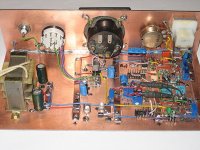
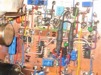
I did build at PCB using islands glued to the surface with cyano glue. The IC's are glued upside down. Please note that the pincount at the bottom view is CW. mark where the pin 1 is with a felt pen. Building this way gives a very good ground plane and one can build very fast just following the diagram.
The circuit uses cheap aliexpress opamps with good results.
The power should be between +/- 6VDC and +/- 7,5 VDC, well stabilsed and low impedance. I used 78L05 and 79L05 with a red LED in the common in order to raise the voltage to 6,6VDC
because I wanted to tune automatically, I used a circuit that is not critical for parts value's. The meter was designed and build in a few days and does not pretend to be an instrument to measure down to unbelievable low value's, it is just a practical tool for the design of my amps.
The THD meter is finished and works as expected. I use 700 Hz in order to have all components and expected harmonics well in the audio band.
First of all, the diagram
The input goes via a 500K pot to an opamp in order to have a high input impedance. The input level should be adjusted to 200 mV eff, a meter circuit is included wich should be calibrated . Screem the input from the meter circuit, the signal at the meter may introduce some capacitively coupled distorsion into the input. The input to the filter is also led to a comparator in order to have a reference signal for the nulling loops.
The filter is a variable state filter connected such that there is little dependence of component value's. Normal E12 resistors and caps can be used. The filter has a notch output (via an amplifier), a band pass output (BP) and a 90-degrees output, used in the nulling loops.
When build as such, the filter will give you approx a notch with a factor 50 - 100 attenuation, wich is not sufficient for most THD measurements.
But the Notch output is in counter phase with the BP output, so when a small amount of BP signal is added to the NOTCH output, one can get a very deep null. But the frequency becomes extremely sharp ( a part of a Hz) and tuning becomes almost impossible.
Therefore, I added a control loop for the frequency by adjusting the drive resistor of the second integrator with a LDR driven by a red LED. Both are mounted together in a piece of shrink sleeve. The tuning information comes from the phase of the REF signal and the 90 degrees signal. These are 90 degrees out of phase when tuned correctly. I used the pahse comparator 1 of CD4046 PLL circuits for simplicity
In order to test, first test the filter without the LDR for the frequency loop and the nulling loop connected. One should get a Notch at approx 6500 Hz. Set the DC NULL so that there is no DC at the NOTCH output.
Now adjust the loop gain for the freq. loop to midrange and connect the LDR for the freq. loop. The tuning should go to apprix 700 Hz and the loop will have much less frequency dependency. Now increase the loop gain until the loop starts oscillating and back-off a little.
There should be a remainder of the 700 Hz visible at the NOTCH output.
This remainder can be nulled by a variable resistor of 100 K between the NOTCH and the BP to add a sample of BP signal to the NOTCH signal. You should adjust between both the FREQ adjustment and this resistor to get the deepest null, but again it is a very sharp null. So the NULLING loop is connected also using a LDR wich is connected between the BP and the NOTCH. (instead of the proposed variable resistor.)
The Null should inmedeately become very deep. Now adjust the FREQ ADJ trim pot for minimum NOTCH signal and only the harmonics of the 700 Hz frequency source are now visible. Adjust the nulling loop gain at the max gain possible without oscillatory effects.
Calibration
Use a low distorsion generator at 700 Hz and adjust the level.
Let the meter warm up for 10 minutes (always do before use) and fine adjust the freq. adjust to have the deepest null.
The output meter should be calibrated for 0,1% FS, 1%FS and 10% FS, but calibratio at 1% FS is sufficient.
The null should be less than 0,05% THD. Mine is 0,03% for my LEVELL generator.
Now define the generator output impedance (mine is 600 Ohms ) and connect a second generator via a resistor of 100X the generator impedance (so e.g. 56 kOhm) to the generator output. Adjust the second generator for the same output level as the 700 Hz generator but at a frequency between 1,4 and 10 kHz. This should add 1% distorsion to the 700 Hz signal and adjust the NOTCH GAIN until the meter shows 1%
BUILDING
I did build at PCB using islands glued to the surface with cyano glue. The IC's are glued upside down. Please note that the pincount at the bottom view is CW. mark where the pin 1 is with a felt pen. Building this way gives a very good ground plane and one can build very fast just following the diagram.
The circuit uses cheap aliexpress opamps with good results.
The power should be between +/- 6VDC and +/- 7,5 VDC, well stabilsed and low impedance. I used 78L05 and 79L05 with a red LED in the common in order to raise the voltage to 6,6VDC
Attachments
")
That is really a good effort... the auto-null is especially interesting.
How low can you go with this (thd)?? What would be required to have .001% thd meter?
I like you direct wiring to the pins...
THx-RNMarsh
0.001% will be a challenge. The deep null will require less drift and less crosstalk. When you build a little more widespread in order to diminsh the capacitive crosstalk between the input meter and the input and if you use better opamps like the chinese NE5532 I use, you may be in business. But even noise due detection of local transmitters and 50Hz hum may become a fight. So you may need to limit the input to e.g. 30 kHz with a simple RC filter
I have a local MW station very close and it gives me some problems.
The automatic loop gain has to be maximum possible, so it may be helpfull to add a little complexity in the feedback by adding a extra pole to avoid loop ocillation at very high loopgains. Or you should accept less autotuning range. I can change the frequency +/- 1% without loosing acuracy and remain within 0,05% when changing +/- 4%
I think that you should build like I do in order to have an ideal groundplane and minimize capacitive couplings. A PCB will for sure be a BIG fight.
It never was my goal to be better than 0.01%.
yes, it would be pushing everything. How would two notch filters help at near same freq?
-RNM
If you add an other automatic filter, there is not sufficient signal at the 90 degrees output to drive the CD4047. Perhaps if you amplify that signal it works. You can use the REF signal of the first filter also for the second filter.
But you should put a nulling loop (adding BP to the NOTCH) ONLY at the second filter otherwise there is not sufficient signal to null. And even than you may need to amplify the NOTCH signal to the CD4046 of the second filter a little more than I do. But that is no problem, with two filters you add an other 20 - 30 dB.
I advise to build a filter without a nulling loop, only with a frequency loop and measure what kind of signals you have and if you have to amplify befor entering the second filter. It should be approx 2 - 10 mV.
But you need to add only 10 - 15 dB, so it may be possible to do that with an after-filter without tuning
Interesting project to try
Thought again. When you have a first filter without a nulling loop, only with a frequency loop, you have approx 5 mV of signal left. When you just amplify that to 200 mV, you can add the filter as described behind it and use the first REF signal for the second filter. I think that will work.
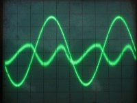
attached a photo of the distorsion of my LEVELL generator of 0,025% The trace is a little fat due to noise and hum, mainly from the generator. So you need a VERY good generator to test and I think a little better opamps (or originals, no Chinese)
I found a little gremlin. It doesn't impaire the functioning, but not nice.
In the NULLING LOOP the Notch signal goes to an amplifier coupled via 3,3uF to a limiter.
Please set 2k2 in series with the 3,3 uF, the first amp doen't like the load.
Kind regards
Nico
I found a little gremlin. It doesn't impaire the functioning, but not nice.
In the NULLING LOOP the Notch signal goes to an amplifier coupled via 3,3uF to a limiter.
Please set 2k2 in series with the 3,3 uF, the first amp doen't like the load.
Kind regards
Nico
Attachments
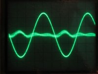
I measured a small Aliexpress LM386 amp loaded with 8 Ohms. The pic shows mainly second harmonic distorsion of 2,2%, out of phase with the 700 Hz signal. I think that means that the distorsion originates mainly from the driver stages, not from the final due to unbalance.
Much fun to play around with the filter and very interesting.
Much fun to play around with the filter and very interesting.
Attachments
Last edited:
- Status
- This old topic is closed. If you want to reopen this topic, contact a moderator using the "Report Post" button.
- Home
- Design & Build
- Equipment & Tools
- simple automatic notch filter.