Considering the interest in building a phase noise measurement tool to test the oscillators we design for digital audio, I start this thread to investigate the opportunity to develop such this system.
Commercial tools are available but they are too expensive and not affordable for the hobbyist.
Gerhard, Demian, Ambrosia168 and all the other members, please use this thread for the discussion about the project.
Commercial tools are available but they are too expensive and not affordable for the hobbyist.
Gerhard, Demian, Ambrosia168 and all the other members, please use this thread for the discussion about the project.
Andrea Mori wrote in the oscillator thread:
I don't own an FFT, can you suggest a suitable soundcard and the right software (cheap) to do the test? Or other inexpensive gear to do this?
I heard people say that Juli@ cards would be quite ok. I did some experiments
with an external USB soundcard Terratec DMX6fire USB but the driver situation
then was hopeless. Probably that has been solved over the years.
I also have a DG6SAQ vector network analyzer that works as a sound device and that
has own audio codecs. In the beginning there was some nuisance now and then
when Windows knew better about the proper use of sound devices.
The whole board of the VNWA is maybe 10 * 6 cm, so there cannot be too much
involved with the codecs. There is even an onboard hub so it needs only 1 USB cable.
Someone has teamed an external ADC chip to a BeagleBoneBlack and he
controls it from a smartphone. Quite impressive.
< https://www.element14.com/community...-high-speed-data-acquisition-and-web-based-ui >
For me, the problem is solved with the Agilent 89441A. It is available sometimes
quite cheaply because it's underrated. Most people think one can use it only to
develop the pre-previous generation of cell phones. The phone manufacturers need
better stuff for LTE, so the old ones are on the market. When the RF unit is
missing, that is no problem for you since YOUR signals need not to be received
from the air. But make sure you get the dual channel option and the source module
so you can make Bode plots.
regards, Gerhard
Demian Martin wrote in the oscillator thread:
remaining questions on this-
1) reference noise source- couldn't a voltage modulated oscillator provide a suitable reference if all the details are worked out? A sinusoidal modulation with peak voltage matching the frequency offset from a known voltage could be translated into a known phase noise level? Getting some reference is important. I think there is something in the Wenzel lit on that issue as well. They also have a procedure for manual calibration that is not real easy to follow on paper.
You cannot wideband modulate a crystal oscillator. Maybe a few Hz. And it would
be really Fm modulation. That could be looked upon as phase modulation also,
the two are linked by integrating/differentiating but the PN then would be different
for each offset frequency.
Modulating the osc is like constantly accelerating / decelerating a flywheel,
and the crystal is quite heavy a flywheel.
It would be easier to get phase modulation from a RC lowpass, where the
C is a varactor diode. That is really done.
I got the idea for the PN standard from
< http://tf.nist.gov/general/pdf/1000.pdf >
And they say that taxpayer's money is wasted...
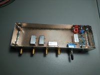
Really, there is not much to it. In the picture, there are 2 power splitters/combiners
MCL PSC2-1. The left one is used to split an incoming test carrier into two outputs.
One leaves the box on the leftmost SMA connector immediately as the ref signal.
The other output goes to the right PSC2-1, this time used as a combiner. The
second input comes from the noise source. The output of the combiner is the
contaminated version of the reference.
With the switch & the two relays I can select high/low noise or an external dirt
input that can double as "clean" with a 50 Ohm termination instead.
The noise source is a 50 Ohm resistor whose voltage noise is amplified with
2 LMH6702. Probably the first amplifier adds more noise than the resistor, but
the only thing that counts is that it is constant and reproducible.
Note that there are still some wires missing in the box.
With the addition of a lambda/4 coax cable delay, a ring mixer and a sensitive
FFT analyzer you can already measure the added phase noise of amplifiers.
That is actually much easier than for oscillators since there is only 1 frequency
involved, no need for PLLs, VCXOs and other stuff.
2) Could we start with 24.568/22.5792 MHz and a multiplier/divider for all the variations? or do we need discrete oscillators for each frequency?
Each halving of the frequency makes it 6 dB easier for use as a reference
and 6 dB harder for use as a test object.
3) Do we need an input signal conditioning stage? A limiting amplifier to get the necessary level and remove amplitude noise?[/QUOTE]
You get rid of the amplitude noise already by the use of the lambda/4 delay line.
Of course you can also measure the amplitude noise by enforcing 0° phase
difference at the mixer inputs.
Having some amplifiers capable of 17 dBm or more is handy.
remaining questions on this-
1) reference noise source- couldn't a voltage modulated oscillator provide a suitable reference if all the details are worked out? A sinusoidal modulation with peak voltage matching the frequency offset from a known voltage could be translated into a known phase noise level? Getting some reference is important. I think there is something in the Wenzel lit on that issue as well. They also have a procedure for manual calibration that is not real easy to follow on paper.
You cannot wideband modulate a crystal oscillator. Maybe a few Hz. And it would
be really Fm modulation. That could be looked upon as phase modulation also,
the two are linked by integrating/differentiating but the PN then would be different
for each offset frequency.
Modulating the osc is like constantly accelerating / decelerating a flywheel,
and the crystal is quite heavy a flywheel.
It would be easier to get phase modulation from a RC lowpass, where the
C is a varactor diode. That is really done.
I got the idea for the PN standard from
< http://tf.nist.gov/general/pdf/1000.pdf >
And they say that taxpayer's money is wasted...
Really, there is not much to it. In the picture, there are 2 power splitters/combiners
MCL PSC2-1. The left one is used to split an incoming test carrier into two outputs.
One leaves the box on the leftmost SMA connector immediately as the ref signal.
The other output goes to the right PSC2-1, this time used as a combiner. The
second input comes from the noise source. The output of the combiner is the
contaminated version of the reference.
With the switch & the two relays I can select high/low noise or an external dirt
input that can double as "clean" with a 50 Ohm termination instead.
The noise source is a 50 Ohm resistor whose voltage noise is amplified with
2 LMH6702. Probably the first amplifier adds more noise than the resistor, but
the only thing that counts is that it is constant and reproducible.
Note that there are still some wires missing in the box.
With the addition of a lambda/4 coax cable delay, a ring mixer and a sensitive
FFT analyzer you can already measure the added phase noise of amplifiers.
That is actually much easier than for oscillators since there is only 1 frequency
involved, no need for PLLs, VCXOs and other stuff.
2) Could we start with 24.568/22.5792 MHz and a multiplier/divider for all the variations? or do we need discrete oscillators for each frequency?
Each halving of the frequency makes it 6 dB easier for use as a reference
and 6 dB harder for use as a test object.
3) Do we need an input signal conditioning stage? A limiting amplifier to get the necessary level and remove amplitude noise?[/QUOTE]
You get rid of the amplitude noise already by the use of the lambda/4 delay line.
Of course you can also measure the amplitude noise by enforcing 0° phase
difference at the mixer inputs.
Having some amplifiers capable of 17 dBm or more is handy.
Attachments
Last edited:
Good doc. I'll need to study it more but it seems to be on the right track. The stuff about vibration sensitivity may be far more important than the other stuff we are looking at.
Gerhard:
The Juli@ is a very good soundcard. Its limited by the performance of the ADC and DAC but external ADC and DAC through the spdif interface work well. my trick of injection locking the crystals works well and keeps the card working when the external oscillator is missing.
I looked at the Agilent and the prices I saw were still quite high. Its a nice box. It highlights what happens when technology moves on. Yesterday's $100K box is worth little more than scrap.
Further general comment:
What I would really like is to be able to measure with some confidence and accuracy the jitter/noise impact on the audio output. Perfect oscillator in a poorly implemented DAC may not get the desired results. The DAC may have internal jitter issues that swamp all these efforts. I can get really good results from USB DAC's already. How do I confirm the improvements from better oscillators, if there are any?
What I would really like is to be able to measure with some confidence and accuracy the jitter/noise impact on the audio output. Perfect oscillator in a poorly implemented DAC may not get the desired results. The DAC may have internal jitter issues that swamp all these efforts. I can get really good results from USB DAC's already. How do I confirm the improvements from better oscillators, if there are any?
Good doc. I'll need to study it more but it seems to be on the right track. The stuff about vibration sensitivity may be far more important than the other stuff we are looking at.
Good vibration isolation particularly for very low frequency vibration is not trivial (and would have its effect on the very close in phase noise we are most concerned with)
The problem is that regular springs couple. Roller balls are great for horizontal isolation but vertical is more of a challenge. The graviton measuring folks have literature on this. For example: http://www.gravity.uwa.edu.au/docs/HonorThesis/Terran_Thesis.pdf
The "Euler spring" is an interesting design that can be constructed in a number of ways including carbon fiber tubes arranged in tetrahedra or spiral.
Jonathan
Biggest challenge is the lack of mass of crystals or crystal oscillators. Maybe imbedding in a cast iron block on even rubber would be enough. Wenzel has stuff on active vibration stabilization. The crystals are more sensitive in one axis so its less of a challenge than it first seems.
Sent from my LG-H811 using Tapatalk
Sent from my LG-H811 using Tapatalk
Maybe imbedding in a cast iron block on even rubber would be enough.
... or how about Panzerholz ..? Very quick damping and reasonably frequency linear as well:
https://www.lessloss.com/page.html?id=80 .... e.g. 2/3 down the webpage.
Cheers,
Jesper
Biggest challenge is the lack of mass of crystals or crystal oscillators. Maybe imbedding in a cast iron block on even rubber would be enough. Wenzel has stuff on active vibration stabilization. The crystals are more sensitive in one axis so its less of a challenge than it first seems.
The vibrations of concern come from the earth itself. The simplest setup is an 18" 3/4" birch plywood on top of an inner tube. Then roller blocks. (2" disc bowls in 7071 alum and SiC ball bearings) Then 3/4 inch slab of marble into which equipment is placed.
The inner tube does couple low frequency vertical waves/vibrations. The marble block supplies mass -- yes the heavier the better within reason.
This setup is easy to do and ideal for a workbench. Euler springs for better vertical isolation would be better than inner tube. Other spring like isolators including magnets are just springs and couple the vibrations the same way -- more expensive than inner tubes but not fundamentally better.
Active -- interesting probably a whole 'nother order of complexity/development.
I used to use a granite surface plate a pneumatic isolators for phono. Worked well for structure born vibration. But acoustical stuff needs addressing.
You can actively correct for vibration, kind of like a txco or actively suspend the oscillator. Both intersting but nontrivial projects.
Sent from my LG-H811 using Tapatalk
You can actively correct for vibration, kind of like a txco or actively suspend the oscillator. Both intersting but nontrivial projects.
Sent from my LG-H811 using Tapatalk
Here is the problem detecting acoustic and vibration modulation. The standard tests require long acquisitions which make catching small modulations that may be intermittent difficult. Without a signal in the audio output there can be no effect from modulation so you need a continuous stable signal. Just doing an FFT of that may not see the modulation. What I propose and will try is to generate a continuous tone at something like 3.14 KHz that a wow and flutter meter is sensitive to. Then dig out the meter (buried in storage) and see if sees any modulation. I'm open to easier/better options.
Here is the problem detecting acoustic and vibration modulation. The standard tests require long acquisitions which make catching small modulations that may be intermittent difficult. Without a signal in the audio output there can be no effect from modulation so you need a continuous stable signal. Just doing an FFT of that may not see the modulation. What I propose and will try is to generate a continuous tone at something like 3.14 KHz that a wow and flutter meter is sensitive to. Then dig out the meter (buried in storage) and see if sees any modulation. I'm open to easier/better options.
Why not just do a phase noise plot with and without vibration isolation?
Simply put I don't know enough about how the noise would show itself. I don't have a phase noise test set. Also it really needs to be tested as a system. The PCB assembly and the casework will all affect the vibration and what happens at the crystal. That's why looking at the analog output seems necessary.
That is so typical for audio, that one of the minor aspects is singled out,
blown up beyond any proportion and that is then the benchmark in a
community. Be it FETs, use of iron in boxes, but in transformers it is ok,
but ferrite is bad again. OMG.
I can assure you that granite does not play a role in commercial oscillator design,
and a good oscillator can deliver stellar performance, just sitting on a lab table
but shielded from moving air.
Vibration sensitivity is a problem when you build a radar for a helicopter
where a crystal is multiplied up to 10 GHz and you get Doppler echoes from
slowly moving targets that are just 5 Hz off the transmitted carrier.
I recommend that from Mr. Driscoll himself:
< http://www.ieee-uffc.org/frequency-control/learning/2003_IEEE_Tutorial.PDF >
including funny oscillators with multiple crystals mechanically rotated by 180°...
regards, Gerhard
Not exactly the phase noise measurement information, but a "Crystal Motional Parameters
A Comparison of Measurement Approaches" document. Some very good methods of testing the motional parameters that influence the phase noise.
http://www.cliftonlaboratories.com/Documents/Crystal%20Motional%20Parameters.pdf
A Comparison of Measurement Approaches" document. Some very good methods of testing the motional parameters that influence the phase noise.
http://www.cliftonlaboratories.com/Documents/Crystal%20Motional%20Parameters.pdf
HP 3048A Software
I've acquired the hardware for the HP 3048a which, using the 3561a signal analyzer can measure down to 125microHz offsets! The software looks like it can be done a few different ways -- does anyone have experience with software options?:
1) MSDOS 6.0 based on antique hardware
2) HP Basic on ?? -- HTBasic seems really really expensive -- anything cheap available?
3) PM3048 on Windows
MSDOS 6.0 is the least of your problems. There are distribution images
on the net, Microsoft probably doesn't care anymore.
You should try the timenuts group on febo.com. Restoring an
old 3048 will be a most welcome topic there.
MSDOS 6.0 is no problem, nor building a circa 1990 PC with an ISA HP/GPIB card to run the software. I've got all that.
You've been using an 89441A, right? My question was concerning the different platforms to run the HP software (BASIC or not).
This old equipment is easily obtainable at very attractive prices with just a little patience (or friends with labs
") ... many times its the PSU which goes bad either due to an old tantalum cap that HP favored at the time, or else a bad diode etc. but the specs on the older equipment are still terrific for lower frequency work ... and that means under a few Ghz.
... many times its the PSU which goes bad either due to an old tantalum cap that HP favored at the time, or else a bad diode etc. but the specs on the older equipment are still terrific for lower frequency work ... and that means under a few Ghz.How are you doing your own programming?
Will certainly check out [timenuts]
On the entirely opposite technology end would be using an FPGA and high speed ADC to do the phase comparisons but looking at the specs, the 3048A might still be unbeatable?
On my daytime job we have a E5052B and another project member
has a R&S FSUP (?) which gave nearly identical results. I'd like
to keep that capability for myself, at least for some fixed frequencies
like 5, 10, 100 MHz. (being a free lancer)
I use the 49441A currently as an FFT analyzer after preamplifiers of
my own for baseband; I'm still stuck at 190pV/rtHz or so, already too
good after ring mixers, but I'd like to break the 100 pV barrier.... It eats
up lots of time.
I control the 49441A over the LAN. It took a BNC-LAN to twisted pair
converter for $25, but it works really good. I just open port 5xxx on
192.168.1.111 and feed it GPIB commands and read the results.
I completely ignore its GPIB interface for the finger-thick cable, no
trouble with gpib drivers, AT/PCI-Bus cards and such, had enough of
that 30 years ago.
I think my 89441A has the BASIC option, but I just use it to generate
data and do the FFTs, after that I process the data myself. For me,
BASIC is a dead end, I write my stuff in C; that is probably portable
to the end of time, at least my time. I don't know if the 3048 has
a LAN interface; if it has you can get my sources as a template to
make it work.
One of the beta testers of my preamp has a working 3048, he uses
it at least for baseband measurements. I could pass him your email
address if you want. Personally, I don't have much interest in restoring
a 3048; some of the people who used to use it ( in my daytime job
environment) said it was really cumbersome, and I value their opinion.
But then if your work is putting satellites into space, the pockets are
much deeper and your perspective quickly adjusts to that.
I have a ADC / FPGA / DSP project with 2.4 GHz sampling rate
on the back burner, have done similar things but I must first
flush the pipeline.
I have been killing a few trees around my house with a chain saw today
and put two of them into a container; I'm pretty well done for today.
My back hurts. Not the appropriate job for someone who is used to solder
under the microscope.
regards, Gerhard
Last edited:
- Status
- This old topic is closed. If you want to reopen this topic, contact a moderator using the "Report Post" button.
- Home
- Design & Build
- Equipment & Tools
- Building a phase noise measurement system for digital audio