Simply put I don't know enough about how the noise would show itself. I don't have a phase noise test set. Also it really needs to be tested as a system. The PCB assembly and the casework will all affect the vibration and what happens at the crystal. That's why looking at the analog output seems necessary.
Why not use led as a damping material?
On my daytime job we have a E5052B and another project member
has a R&S FSUP (?) which gave nearly identical results. I'd like
to keep that capability for myself, at least for some fixed frequencies
like 5, 10, 100 MHz. (being a free lancer)
I use the 49441A currently as an FFT analyzer after preamplifiers of
my own for baseband; I'm still stuck at 190pV/rtHz or so, already too
good after ring mixers, but I'd like to break the 100 pV barrier.... It eats
up lots of time.
I have access to an 89441a and gulp ... thought that BNC connector was an extra RF input of some sort ... should have read the entire manual, I was focussed on replacing a couple caps to get it recovered... as I mentioned, these wonderful pieces of equipment can be had at close to scrap metal prices if one is willing to do a little repair. In any case I'm hitting close to 90% on repairing those PSUs to the point where I *start* by replacing the diodes and caps, and *then* testing...
I control the 49441A over the LAN. It took a BNC-LAN to twisted pair
converter for $25, but it works really good. I just open port 5xxx on
192.168.1.111 and feed it GPIB commands and read the results.
I completely ignore its GPIB interface for the finger-thick cable, no
trouble with gpib drivers, AT/PCI-Bus cards and such, had enough of
that 30 years ago.
That's an elegant solution, though my 100mHz pentium with an ISA HP-IB card is part of my technology museum (not entirely original specs as missing the circa 1980s tantalum caps
") Of course BASIC is a dead end, but I have this warm nostalgic feeling knowing that it is running somewhere, somehow.
Of course BASIC is a dead end, but I have this warm nostalgic feeling knowing that it is running somewhere, somehow.I would very much appreciate your C sources.
One of the beta testers of my preamp has a working 3048, he uses
it at least for baseband measurements. I could pass him your email
address if you want. Personally, I don't have much interest in restoring
a 3048; some of the people who used to use it ( in my daytime job
environment) said it was really cumbersome, and I value their opinion.
But then if your work is putting satellites into space, the pockets are
much deeper and your perspective quickly adjusts to that.
Fair enough. No doubt more cumbersome than a direct LAN attachment. The 3048a is heavily dependent on software which prompted my original question -- yes I would appreciate assistance or information in that regard.
I have a ADC / FPGA / DSP project with 2.4 GHz sampling rate
on the back burner, have done similar things but I must first
flush the pipeline.
I have been killing a few trees around my house with a chain saw today
and put two of them into a container; I'm pretty well done for today.
My back hurts. Not the appropriate job for someone who is used to solder
under the microscope.
Your yard sounds like mine, and I spend most of my day also with a stereo microscope -- but I stand
What about oscillators metrology with SDR?
https://pdfs.semanticscholar.org/6821/b2e600393286ea178dc23b4f533261c904a3.pdf
https://pdfs.semanticscholar.org/6821/b2e600393286ea178dc23b4f533261c904a3.pdf
Take a look at the Timepod, designed by J.Miles (who is on the time nuts list) and now sold by Symmetricom, really now by MicroSemi.
A wonderful thing.
Just do it, too expensive for an hobbist.
Thanks for the tips on 10base2 ... that was used in the days where I was either working from a VT100 or PC not connected to Ethernet ... or perhaps, just perhaps, the VAXstation was networked that way, never occurred to me to look
Yes the HP-Basic is available, just probably don't have a Series 200 to run on ... but there is also the HTBasic software so a few options.
Moving forward, being able to issue commands over the network is very appealing and probably at some point could get a DOS 486 with a network card and a HPIB card to act as an Ethernet gateway for this old equipment.
The "SDR" approach is very interesting and one of the goals is to verify the measurements against analog. SubHz is where it gets less than trivial -- not that its essential but nonetheless. The FPGA SOCs are getting much more affordable including boards designed for SDR specifically.
Rutgers DC receiver would be to complicated to build it for multiple frequency's, needed in digital audio. Looking how he realizing the reference oscillator, damping and things.
Maybe a cheap way could be to use an old color TV color PLL section, I think some dedicated IC's out there which do that job. Also one could investigate the possibility to use a shortwave receiver ,which would receive the DUT oscillator and use a good quality crystal oscillator for the shortwave radio's BFO, than analyze the audio output. Radio's are usually good to 30MHz, to cover the usual CDP oscillators. In reality 1Audio is right, the main thing in digital audio is the audio output of the DAC , and to see there the Jitter one doesn't need to analyze the oscillator, it's enough to look at the audio, for that we have the Wakibaki's copy of the Jitter test signal here on Diyaudio. It's no good for numerical measurements, but good for comparison of different DAC's and the crystals used in the conversion.
Maybe a cheap way could be to use an old color TV color PLL section, I think some dedicated IC's out there which do that job. Also one could investigate the possibility to use a shortwave receiver ,which would receive the DUT oscillator and use a good quality crystal oscillator for the shortwave radio's BFO, than analyze the audio output. Radio's are usually good to 30MHz, to cover the usual CDP oscillators. In reality 1Audio is right, the main thing in digital audio is the audio output of the DAC , and to see there the Jitter one doesn't need to analyze the oscillator, it's enough to look at the audio, for that we have the Wakibaki's copy of the Jitter test signal here on Diyaudio. It's no good for numerical measurements, but good for comparison of different DAC's and the crystals used in the conversion.
I may have posted this before http://www.diyaudio.com/forums/blogs/1audio/983-fm-tuner-jitter-analysis.html describes how to mod an FM tuner to detect the jitter on a digital audio clock. It uses the harmonics of the clock which have the phase noise multiplied up so its larger and easier to detect. Absolute calibration was beyond me with so many variables (maybe Gerhard could point to a reference for translation of measurement modes from FM to PN to jitter) but its sensitive enough to see very low phase noise. It works for both 44.1 and 48 clocks (and 100 MHz if you are using an ESS chip that way)
@1audio:
... I remember you have posted it before and I thought it looked interesting but got away from it ... hmmm, still interesting ... how good is it in practice? Will it in meaningful ways be able to show something like this (from the TWTMC thread):
http://www.diyaudio.com/forums/digi...se-jitter-crystal-oscillator.html#post4051205
Cheers,
Jesper
I may have posted this before http://www.diyaudio.com/forums/blogs...-analysis.html describes how to mod an FM tuner to detect the jitter on a digital audio clock. It uses the harmonics of the clock which have the phase noise multiplied up so its larger and easier to detect. Absolute calibration was beyond me with so many variables (maybe Gerhard could point to a reference for translation of measurement modes from FM to PN to jitter) but its sensitive enough to see very low phase noise. It works for both 44.1 and 48 clocks (and 100 MHz if you are using an ESS chip that way)
... I remember you have posted it before and I thought it looked interesting but got away from it ... hmmm, still interesting ... how good is it in practice? Will it in meaningful ways be able to show something like this (from the TWTMC thread):
http://www.diyaudio.com/forums/digi...se-jitter-crystal-oscillator.html#post4051205
Cheers,
Jesper
I may have posted this before http://www.diyaudio.com/forums/blogs/1audio/983-fm-tuner-jitter-analysis.html describes how to mod an FM tuner to detect the jitter on a digital audio clock. It uses the harmonics of the clock which have the phase noise multiplied up so its larger and easier to detect. Absolute calibration was beyond me with so many variables (maybe Gerhard could point to a reference for translation of measurement modes from FM to PN to jitter) but its sensitive enough to see very low phase noise. It works for both 44.1 and 48 clocks (and 100 MHz if you are using an ESS chip that way)
I tried that a few years ago, but didn't find it to conclusive, so I give up on it.
Lots of artifacts and noises. In the measurement loop also the FM front end local oscillator, which reduces the accuracy. Maybe I could try it with a player with a 11MHz (or a 10.7MHz one) clock and go in directly to the IF amp, or since the signal level quite high direct to the demodulator, and see what's coming out.
In the last years I measured about 50 CDP's and DAC's of different level of sophistication (dollar) , playing the Jitter test track on them gives a good indication how good they are. To know the exact jitter level of a clock is important to people who manufacturing and selling them to customers, not to an amateur, unless it is your hobby.
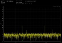
Here's what I measured in 2013 with the help of a Yamaha TX1000U tuner on one of the worst player I come across a Sony CDP-350, although it's jitter performance was OK, and I doubt I would hear any difference anyway.
Pictures: 1. CDP in "Stop" ,16MHz clock on the tuner output, tuner tuned to ca. 97MHz.
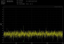
2. CDP with a 16MHz clock plays 1kHz -15dBfs track ,the clock seen on the tuner audio out.
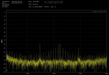
3. CDP plays the -3.5dBfs Jitter test track ,observed on the tuner output.
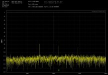
4. same, but -9dBfs Jitter track.
Attachments
-
 Sony CDP350 Stop 16MHz Osc. on the Yamaha TX1000U output.jpg226.3 KB · Views: 449
 -
 SonyCDP350 Play 1kHz -15dBfs track -16MHz on Ya97MHz-S80.jpg238.6 KB · Views: 427
 -
 Sony CDP350 Jitter test Track -3.5dBfs - effect on the 16MHZ Osc on the Yamaha TX1000U output.jpg237.4 KB · Views: 427
 -
 Sony CDP350 Jitter test Track -9dBfs - effect on the 16MHZ Osc on the Yamaha TX1000U output.jpg227.6 KB · Views: 429
Getting quantifiable reading from this is a real undertaking. I would not make the effort even with a calibrated FM source. However you can get a glimpse of the relative performance as was visible above. Another challenge is making sure you aren't getting feedthrough from some other mechanism like grounds.
I used a TX-950 and came directly from the detector amp. The RF and LO are used to get the actual harmonic and reject other noises. You do need to work through all the pieces carefully. The TX-950 has an extremely low noise front end and IF even though it looks cheap. If you take the output after the deemphasis or the stereo decoder it will not be too meaningful.
I used a TX-950 and came directly from the detector amp. The RF and LO are used to get the actual harmonic and reject other noises. You do need to work through all the pieces carefully. The TX-950 has an extremely low noise front end and IF even though it looks cheap. If you take the output after the deemphasis or the stereo decoder it will not be too meaningful.
The CDP was galvanicly insulated from the tuner antenna input.
As you saying a tuner with an multipath output would be better, this way no need to dig in to the tuner.
Also I have eventually access to a Kenwood R5000 SW receiver which has FM out, this could take the fundamental of the CDP's oscillator direct, not the harmonics.
All in all it is no good for measurements, but give an idea in search of the source of the jitter.
Building a PN measuring device.
Hi all,
As some of you may know I have some interest in measuring phase noise and to this end I decided to contact with John Miles (John Miles KE5FX - the designer of the Timepod) to hopefully get some information about what would be feasible to do.
The criteria I listed for a measurement system when I contacted him were:
- My need is to measure phase noise up to ~ 100 kHz carrier offset, however, my main area of interest is the offset frequencies from <1 Hz to ~ 1 kHz. Oscillator frequencies may be from 350 kHz to 50 MHz (very occasionally up to 100 MHz - this is "nice to have"). Phase noise levels may potentially be down to - 120 dBc/Hz at 1 Hz carrier offset. Both sine & square waves are to be measured.
- Additional criteria were low cost and no programming needed as I (currently) don't have such skills. Also, it was an option to output the signal from "Phase noise device" to an "audio analyzer".
John was very helpful in his replies and suggested a quadrature PLL structure as the most optimum solution fitting these criteria.
I understand this is similar to both Herbert's DC receiver:
* https://by-rutgers.nl/PDFiles/DC-receiver.pdf
and part of Wenzel's circuitry here:
http://www.wenzel.com/wp-content/uploads/lowamp.pdf
I also asked him about the tuner approach suggested by 1audio and his reply to this was:
" I'm not a fan of trying to repurpose an FM tuner; the noise floor would not be very good without heavy modification, and there would be a lot of variables to calibrate out/compensate for. Still, the basic idea is exactly right, in that the heart of any PN test set is its (digital or analog) FM demodulator. PM is basically a special case of FM with low-level modulation. " .
So with this in mind I have decided to build either Herbert's DC receiver or Wenzel's amplifier. Which one a.o.t. depends on the feedback here in the next days. It can also be another potentially "better" design in some way that is not too time consuming to layout.
Regarding the Wenzel design it seems to lack the "mixer & reference oscillator section" found in Herbert's DC Receiver - or am I missing something here? It also seems to me that Herbert's DC Receiver might have slightly lower noise levels at very low frequencies given that he uses the LT1028 ...
Whichever of these two is decided upon (I will decide within a few days) I would appreciate your input on possible improvements to these circuits. That could e.g. be overall performance improvements, "ease of use" amendments, critical component selection/updating, or ... ? In case I am to make the Wenzel circuitry the missing parts of this circuitry will also have to be added ... (again, unless I missed something here) ...
What I will do is to make a good PCB layout (most likely two layers) of a "no frills" type. I.e. in case the Wenzel circuitry is chosen it will be with "settable" jumpers and no relays or rotary switches etc.
I reckon this will be sufficient for a DIY'er as I assume the number of measurements to be made will be relatively low. It will also simplify the layout.
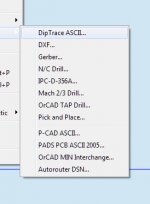
In case others here are interested the layout(s) will be available as pdf.s and/or diptrace files (or files types that may be exported from diptrace - see attachment).
Since I essentially would like to move on with doing PN measurements I - as I mentioned earlier - do not intend this to be a long time project. So please give any inputs you may have before the middle of next week as I most likely will start layouting the PCB(s) at the end of next week.
Cheers
Jesper
Hi all,
As some of you may know I have some interest in measuring phase noise and to this end I decided to contact with John Miles (John Miles KE5FX - the designer of the Timepod) to hopefully get some information about what would be feasible to do.
The criteria I listed for a measurement system when I contacted him were:
- My need is to measure phase noise up to ~ 100 kHz carrier offset, however, my main area of interest is the offset frequencies from <1 Hz to ~ 1 kHz. Oscillator frequencies may be from 350 kHz to 50 MHz (very occasionally up to 100 MHz - this is "nice to have"). Phase noise levels may potentially be down to - 120 dBc/Hz at 1 Hz carrier offset. Both sine & square waves are to be measured.
- Additional criteria were low cost and no programming needed as I (currently) don't have such skills. Also, it was an option to output the signal from "Phase noise device" to an "audio analyzer".
John was very helpful in his replies and suggested a quadrature PLL structure as the most optimum solution fitting these criteria.
I understand this is similar to both Herbert's DC receiver:
* https://by-rutgers.nl/PDFiles/DC-receiver.pdf
and part of Wenzel's circuitry here:
http://www.wenzel.com/wp-content/uploads/lowamp.pdf
I also asked him about the tuner approach suggested by 1audio and his reply to this was:
" I'm not a fan of trying to repurpose an FM tuner; the noise floor would not be very good without heavy modification, and there would be a lot of variables to calibrate out/compensate for. Still, the basic idea is exactly right, in that the heart of any PN test set is its (digital or analog) FM demodulator. PM is basically a special case of FM with low-level modulation. " .
So with this in mind I have decided to build either Herbert's DC receiver or Wenzel's amplifier. Which one a.o.t. depends on the feedback here in the next days. It can also be another potentially "better" design in some way that is not too time consuming to layout.
Regarding the Wenzel design it seems to lack the "mixer & reference oscillator section" found in Herbert's DC Receiver - or am I missing something here? It also seems to me that Herbert's DC Receiver might have slightly lower noise levels at very low frequencies given that he uses the LT1028 ...
Whichever of these two is decided upon (I will decide within a few days) I would appreciate your input on possible improvements to these circuits. That could e.g. be overall performance improvements, "ease of use" amendments, critical component selection/updating, or ... ? In case I am to make the Wenzel circuitry the missing parts of this circuitry will also have to be added ... (again, unless I missed something here) ...
What I will do is to make a good PCB layout (most likely two layers) of a "no frills" type. I.e. in case the Wenzel circuitry is chosen it will be with "settable" jumpers and no relays or rotary switches etc.
I reckon this will be sufficient for a DIY'er as I assume the number of measurements to be made will be relatively low. It will also simplify the layout.
In case others here are interested the layout(s) will be available as pdf.s and/or diptrace files (or files types that may be exported from diptrace - see attachment).
Since I essentially would like to move on with doing PN measurements I - as I mentioned earlier - do not intend this to be a long time project. So please give any inputs you may have before the middle of next week as I most likely will start layouting the PCB(s) at the end of next week.
Cheers
Jesper
Attachments
A phase noise tester for audio crystal oscillators is a waste of time.
I have never seen an ADC or DAC evaluation board which is using something
other than a simple crystal oscillator.
And they get the datasheet performance without any special magic.
It is always the same here. Nobody aks the important question:
How much phase noise is tolerable before SNR degeneration happens?
After answering this question the design of a superduper highres DACs is
simple: use the cheapest crystal oscillator you get and put it near the DAC.
And the sad story is that audio enthusiasts spend a fortune in buying
super low phase noise oscillators and then ruin them by improper
layout and shielding.
Another story is the timing jitter of SPIDF signals. To measure this, you
can not use the crystal phase noise tester. But fortunatly a simpe digital
Osci will do.
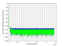
A simple jitter experiment:
In the zip file are two 440 Hz 16 bits/48kHz sine signales with the spectrum
as in the picture.
The second has random jitter of 10 nanoseconds (not picoseconds) added to
the sampling clock.
I will bet the first one a beer, that can hear a difference using the foobar ABX test plugin!
In the zip file are two 440 Hz 16 bits/48kHz sine signales with the spectrum
as in the picture.
The second has random jitter of 10 nanoseconds (not picoseconds) added to
the sampling clock.
I will bet the first one a beer, that can hear a difference using the foobar ABX test plugin!
Attachments
Hi udok,
Thanks for considering ;-)
... Hmmm ... while I respect your opinion I tend to disagree (based on my own experience). Also, did you read Andrea Mori's small listening review of some of the various clocks he has designed? It is in the TWTMC thread, and there's a quote here:
http://www.diyaudio.com/forums/digi...itter-crystal-oscillator-158.html#post5174166
In any case I would say that I am not personally interested in debating this ...
Cheers,
Jesper
- Status
- This old topic is closed. If you want to reopen this topic, contact a moderator using the "Report Post" button.
- Home
- Design & Build
- Equipment & Tools
- Building a phase noise measurement system for digital audio