Hello,
Zfe and Edmond, i can add some jumpers or maybe a small signal relay to bypass input filter if required. These parts may be omitted if direct path is not needed. That would be fine ?
About a daughter board, i don't think it's a good idea to get the best performance. I want to avoid any signal degradation caused by slotted ground plane.
Regards
Frex
As I not want to bypass the filter permanently and all will be, finally, in a case, I would prefer the relay solution.
Firstly, Frex the latest update looks great. Glad to see the isolators on the main ADC board!
I'm still looking in to the RPi performance. To get started I've done the simplest (in terms of my programming effort) approach first - Python with scipy/numpy libraries and the THDN calc that I found in this script - waveform_analysis/thd.py at master * endolith/waveform_analysis * GitHub
I don't agree with everything they're doing in that script (the zero-ing around the fundamental isn't very elegant at all) but the flat top windowing reference in there looks very interesting and worth further investigation. This will be used for performance bench-marking then I will look at improving the calculated results later.
This only uses the scipy FFT functions which are single threaded and don't appear to use the Arm's NEON SIMD instructions.
Benchmarking results as follows using 7 iterations and averaging the execution time. The length of the FFT is memory limited because we've only got 1GB of RAM on RPi. This will limit the ultimate frequency resolution of the results calculated.
rpi below is Raspberry Pi 3B (not the newer 3B+ model 1.2GHz clock vs 1.4GHz clock on 3B+)
xps15 below is my laptop with i7 6700HQ processor and 16GB RAM.
Benchmarking at sample lengths at integer powers of two for convenience using a simulated sine wave data in place of input and benchmarking just the THD+N function.
2**24 16777216 samples -- memory error on Raspberry Pi.
2**23 -> 8388608 samples (approx 5.5sec capture time @ 1536kHz)
THDN
[rpi] 15.3 s ± 449ms per loop
[xps15] 3.51 s ± 32.8 ms per loop
2**22 -> 4194304 samples (approx 2.7sec capture time @ 1536kHz)
[rpi] THDN 7.28 s ± 422 ms per loop
2**21 -> 2097152 samples (approx 1.4sec capture time @ 1536kHz)
[rpi] THDN 3.63 s ± 45.6 ms per loop
2**20 -> 1048576 (approx 0.7sec capture time @ 1536kHz)
[rpi] THDN 1.76 s ± 1.44 ms per loop
[xps15] THDN 418 ms ± 9.79 ms per loop
2**15 -> 32768 (approx 0.02sec capture time @ 1536kHz)
[rpi] THDN 38.4 ms ± 163 µs per loop
Next I will look at setting up FFT calcs to be done using FFTW on the CPU before assessing if there is any benefit to pursuing the GPU approach which I think may be limited to 2**20 points by what I have read of the work that has been done. Consider that any performance improvements will not be linear at best I'm hoping for 2x speedup despite the fact that there are 4cores in RPi. There will be overhead for mutlithreading this calc and then in ultimate case there will also be webserver and UI overhead also. It may be that I'm able to get the RPi to do some measurements but for extreme length FFT (at 1536kHz sample rate long FFTs will come up often I expect) then this may just be captured and high resolution analysis performed offline.
I will continue to investigate opportunities to get performance improvements with the RPi but I think I will proceed with developing the user interface ideas that I've had as discussed earlier. When more details from Frex on the hardware interface I will work towards establishing how to integrate the two so that it is well integrated with the OSVA.
Cheers,
Chris
I'm not sure a Rasberry pi has enough horsepower for the analysis but I may be mistaken.
I'm still looking in to the RPi performance. To get started I've done the simplest (in terms of my programming effort) approach first - Python with scipy/numpy libraries and the THDN calc that I found in this script - waveform_analysis/thd.py at master * endolith/waveform_analysis * GitHub
I don't agree with everything they're doing in that script (the zero-ing around the fundamental isn't very elegant at all) but the flat top windowing reference in there looks very interesting and worth further investigation. This will be used for performance bench-marking then I will look at improving the calculated results later.
This only uses the scipy FFT functions which are single threaded and don't appear to use the Arm's NEON SIMD instructions.
Benchmarking results as follows using 7 iterations and averaging the execution time. The length of the FFT is memory limited because we've only got 1GB of RAM on RPi. This will limit the ultimate frequency resolution of the results calculated.
rpi below is Raspberry Pi 3B (not the newer 3B+ model 1.2GHz clock vs 1.4GHz clock on 3B+)
xps15 below is my laptop with i7 6700HQ processor and 16GB RAM.
Benchmarking at sample lengths at integer powers of two for convenience using a simulated sine wave data in place of input and benchmarking just the THD+N function.
2**24 16777216 samples -- memory error on Raspberry Pi.
2**23 -> 8388608 samples (approx 5.5sec capture time @ 1536kHz)
THDN
[rpi] 15.3 s ± 449ms per loop
[xps15] 3.51 s ± 32.8 ms per loop
2**22 -> 4194304 samples (approx 2.7sec capture time @ 1536kHz)
[rpi] THDN 7.28 s ± 422 ms per loop
2**21 -> 2097152 samples (approx 1.4sec capture time @ 1536kHz)
[rpi] THDN 3.63 s ± 45.6 ms per loop
2**20 -> 1048576 (approx 0.7sec capture time @ 1536kHz)
[rpi] THDN 1.76 s ± 1.44 ms per loop
[xps15] THDN 418 ms ± 9.79 ms per loop
2**15 -> 32768 (approx 0.02sec capture time @ 1536kHz)
[rpi] THDN 38.4 ms ± 163 µs per loop
Next I will look at setting up FFT calcs to be done using FFTW on the CPU before assessing if there is any benefit to pursuing the GPU approach which I think may be limited to 2**20 points by what I have read of the work that has been done. Consider that any performance improvements will not be linear at best I'm hoping for 2x speedup despite the fact that there are 4cores in RPi. There will be overhead for mutlithreading this calc and then in ultimate case there will also be webserver and UI overhead also. It may be that I'm able to get the RPi to do some measurements but for extreme length FFT (at 1536kHz sample rate long FFTs will come up often I expect) then this may just be captured and high resolution analysis performed offline.
I will continue to investigate opportunities to get performance improvements with the RPi but I think I will proceed with developing the user interface ideas that I've had as discussed earlier. When more details from Frex on the hardware interface I will work towards establishing how to integrate the two so that it is well integrated with the OSVA.
Cheers,
Chris
updated synoptic and project news.
Hello,
First, Chris thank you for all these detailed info.
On my side i make some progress and i post below the updated AA2380 board synoptic.
As you can see i started to identify some components and added them on the synoptic.
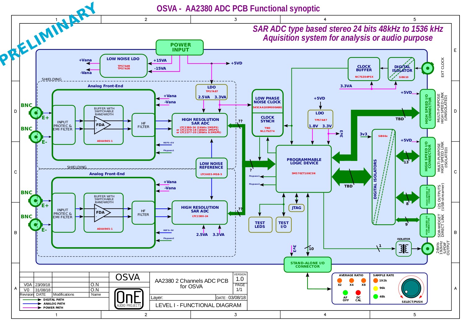
PDF file available here :
OSVA - AA2380V1 ADC Board Synoptic V0A
I also started the schematics, but i will take some work as i use a new CAD.
In fact, i start my first design using Kicad (instead of PCAD) and i must say that for now it's a great DIY tool...
I work a lot also on I/O definition table for external hardware communication
(R-Pi or others), and i will publish it as soon it's ready.
So, the job is in progress...
Regards.
Hello,
First, Chris thank you for all these detailed info.
On my side i make some progress and i post below the updated AA2380 board synoptic.
As you can see i started to identify some components and added them on the synoptic.
PDF file available here :
OSVA - AA2380V1 ADC Board Synoptic V0A
I also started the schematics, but i will take some work as i use a new CAD.
In fact, i start my first design using Kicad (instead of PCAD) and i must say that for now it's a great DIY tool...
I work a lot also on I/O definition table for external hardware communication
(R-Pi or others), and i will publish it as soon it's ready.
So, the job is in progress...
Regards.
I also started the schematics...
So, the job is in progress...
May consider a different asymmetric input configuration/setup, otherwise connecting one of the symmetric input to GND, will pickup none pleased ground current... as seen in some other DIY analyzer

May see how AKM did it with the audio evaluation boards.. or allow an easy input module replacement
Just my 2 cents
Hp
Hello,
JensH,
I had both in mind.
I must say that i wanted try the two solutions before choosing.
Did you have some practical feedback on that and what such transformer
would work fine for 10-50MHz clock isolation ?
Have you tried fast digital isolators also ?
On my side I already used SC947 (From Scientific Conversion) and
they have very good bandwidth and rise time but also very high CMMR .
But they are not cheap.
I also add PLL multiplier in design to be able to generate synchronous
high frequency clock for ADC SPI data reading . I add it in next synoptic i will post very soon.
I hope anticipate many situations for the hardware platform to be able to fit any needs.
Hp,
To avoid any performance degradation (at least he lowest possible), the input stage path is fully differential (as ADC itself).
This is the best way to manage THD products at lowest level.
So, it can be of course used with single-ended input signal.
For this, you will only need to add a 50 Ohms BNC termination on the unused input (but not floating).
Note also that input stage is made very "direct" and "simple" to preserve ADC specs.
Final users needs can be very different (level, filtering, signal mode..) so specifics analog front-end
could be made for each own purpose of end users.
Of course, at the end the way would be that these "third party" specifics analog board
will be shared here to extend possibility of the design.
Regards.
Frex
I have used transformers for high isolation low jitter applications. Use transformers designed for cable TV applications. This is an example: Coilcraft JA4220-AL Surface Mount Wideband RF Transformer It has a bandwidth of 100 KHz to 3 GHz. There are many others. I have also used them to injection lock an existing crystal oscillator, sometimes necessary with this stuff so it won't lock up when the clock is not present. it also is something of a jitter filter.
Perhaps the WBC-series from Coilcraft could be used? E.g. WBC1-1L or WBC1-1TL?
They seem to be available from Mouser. They look a bit pricey too, but I searched for a price on the SC947 and suddenly the WBC-series looked like low cost!
I did some experiments once, using a 10/100 Ethernet transformer, but I never built and characterized a complete circuit. But they are definitely cheap.
This part should work: PWB1015LB Coilcraft | Mouser Its not cheap at $2.25 but nothing compared to the SC947. Also the required frequency range would be higher for master clock. The part I have used in the past is now listed as obsolete. . .
Depending on the application I might look at resonating the primary and secondary to narrow the bandwidth to the target range and reduce the wideband phase noise.
The network interface transformer is a really interesting option for SPDIF since they have pretty aggressive common mode isolation. And they were pretty cheap. Probably not any more. No market for 10-100 LAN.
OK fine.
The JA4220 is very cheap but i think inductance is too low and driving could be an issue.
There is also nos specs about common mode rejection that can be the major contribution in real system jitter.
Like JensH, I think say that LAN transformer can be a good idea.
Inductance are not too low, bandwidth is high and CMRR is good in broad frequency range.
They are also not too expensive.
I think i will order some of them and make some measurements.
I have also SC947 transformer for compare.
Frex
OK fine.
The JA4220 is very cheap but i think inductance is too low and driving could be an issue.
There is also nos specs about common mode rejection that can be the major contribution in real system jitter.
Like JensH, I think say that LAN transformer can be a good idea.
Inductance are not too low, bandwidth is high and CMRR is good in broad frequency range.
They are also not too expensive.
I think i will order some of them and make some measurements.
I have also SC947 transformer for compare.
Frex
I don't know if the performance is better or worse, but you could consider taking the clock in and converting it to LVDS for distribution and isolating it with ADN4650. There is no phase noise vs frequency graph though, but the HF jitter specs look ok. Probably unnecessary but you can then distribute the clock as LVDS internally.
LTC2500
We are also involved in a precision application with two LTC2500 32-bit ADCs to measure DC levels related to temperature change. I wonder if anyone has worked with a front end design that even approaches this resolution, especially at DC and over time. We've done similar work before and used the INA103 instrumentation amp, but found a limit around 18 - 19 bits.
We are also involved in a precision application with two LTC2500 32-bit ADCs to measure DC levels related to temperature change. I wonder if anyone has worked with a front end design that even approaches this resolution, especially at DC and over time. We've done similar work before and used the INA103 instrumentation amp, but found a limit around 18 - 19 bits.
It may be that I'm able to get the RPi to do some measurements but for extreme length FFT (at 1536kHz sample rate long FFTs will come up often I expect) then this may just be captured and high resolution analysis performed offline.
Cheers,
Chris
-RNM
We are also involved in a precision application with two LTC2500 32-bit ADCs to measure DC levels related to temperature change. I wonder if anyone has worked with a front end design that even approaches this resolution, especially at DC and over time. We've done similar work before and used the INA103 instrumentation amp, but found a limit around 18 - 19 bits.
How could they ever validate the 32 bit claim? 24 bits is .06PPM which is well below the resolution of the best 7 digit KV dividers. A front end for 32 bits would be amazing and would wander all over with the occasional cosmic ray in the nearest mile. . .
Actually doing the noise calculation will lead to impossible values for source resistance and voltage/current requirements.
Yeah, from the datasheet -
The dynamic range of the LTC2500-32’s 32-bit ADC core is 104dB. The dynamic range of the filtered output improves by 6dB for every 4× increase in
the down-sampling factor.
They quote 148dB DNR at 61sps using a huge downsampling factor.
Higher resolution and bandwidth
The only method is by lowering the bandwidth to 5sps or less, and even then it's only 28 bits or so. We need as much resolution as possible for precision current monitoring at up to 1Msps, a bit different. Have used parallel amps to lower noise and moving window averaging, but need still better performance. Fortunately our source is low impedance - 5 ohms or less. The INA103 has excellent linearity but is pretty old now.
How could they ever validate the 32 bit claim? 24 bits is .06PPM which is well below the resolution of the best 7 digit KV dividers. A front end for 32 bits would be amazing and would wander all over with the occasional cosmic ray in the nearest mile. . .
Actually doing the noise calculation will lead to impossible values for source resistance and voltage/current requirements.
The only method is by lowering the bandwidth to 5sps or less, and even then it's only 28 bits or so. We need as much resolution as possible for precision current monitoring at up to 1Msps, a bit different. Have used parallel amps to lower noise and moving window averaging, but need still better performance. Fortunately our source is low impedance - 5 ohms or less. The INA103 has excellent linearity but is pretty old now.
Hello all,
I updated again the AA2380 ADC board synoptic, as I started drawing a real schematic and choosing some parts.
I added an (optional) relay to allow easy switch from differential to single-ended input.
Stand alone led indicators and encoder allow to select :
Sample rate (48/96/192k)
Averaging ratio (1 to 32x)
Anti-alias filter bypass on/off
DC calibration process (offset removal)
Single-ended or differential input selection.
Some jumpers on board will allow to switch from internal or external clock reference, and maybe others configurations.
The new AA2380 general synoptic (V0B).
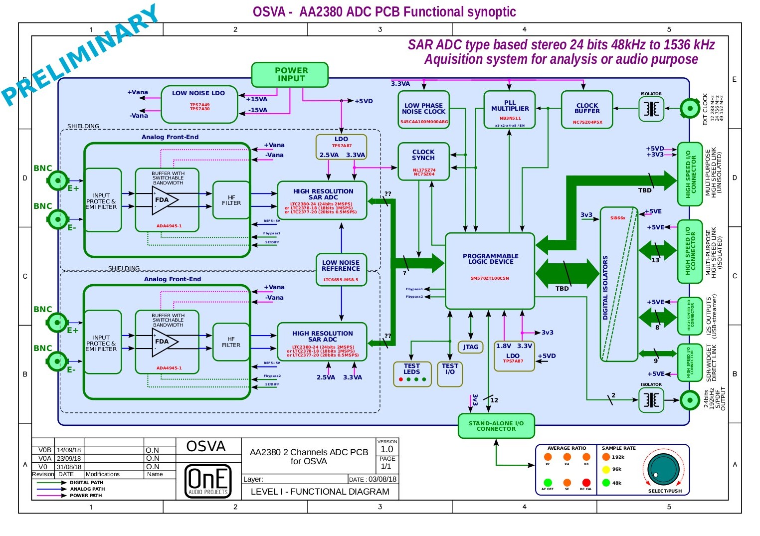
PDF version : AA2380_synoptic-V0B
About isolators for external clock, i ordered LAN and RF transformers (i already have the SC947-02)
and i will test it when received. I prepare for now the test setup (for rise time and CMRR test).
Chris,
The LVDS isolator is pretty expensive but i thanked too about LVDS solution, at least for the on board oscillator.
And so, i choose on that can be LVDS output or not (Si545 series).
Descon,
I already seen the LT2500 but i must say that i would be curious to know with more precision
what is the final application require such resolution with 1MSPS !
Could you tell us more ? That can help to discuss.
Did you use averaging (how many) to improve SNR, or not, to preserve bandwidth ?
About the front-end, we must know what is the input signal source (from what it come)
to know what main parameters are involved in the analog front-end design.
Like :
Input impedance ? (I see 5 Ohms)
required Input bias current ?
Input voltage range ?
single-ended or differential ?
Bandwidth ?
and probably others...
Can you share with us these information ?
Note that i think that it would be better to continue to discuss of this on a new dedicated thread to avoid mix and confusing.
Best regards.
Frex
I updated again the AA2380 ADC board synoptic, as I started drawing a real schematic and choosing some parts.
I added an (optional) relay to allow easy switch from differential to single-ended input.
Stand alone led indicators and encoder allow to select :
Sample rate (48/96/192k)
Averaging ratio (1 to 32x)
Anti-alias filter bypass on/off
DC calibration process (offset removal)
Single-ended or differential input selection.
Some jumpers on board will allow to switch from internal or external clock reference, and maybe others configurations.
The new AA2380 general synoptic (V0B).
PDF version : AA2380_synoptic-V0B
About isolators for external clock, i ordered LAN and RF transformers (i already have the SC947-02)
and i will test it when received. I prepare for now the test setup (for rise time and CMRR test).
Chris,
The LVDS isolator is pretty expensive but i thanked too about LVDS solution, at least for the on board oscillator.
And so, i choose on that can be LVDS output or not (Si545 series).
Descon,
I already seen the LT2500 but i must say that i would be curious to know with more precision
what is the final application require such resolution with 1MSPS !
Could you tell us more ? That can help to discuss.
Did you use averaging (how many) to improve SNR, or not, to preserve bandwidth ?
About the front-end, we must know what is the input signal source (from what it come)
to know what main parameters are involved in the analog front-end design.
Like :
Input impedance ? (I see 5 Ohms)
required Input bias current ?
Input voltage range ?
single-ended or differential ?
Bandwidth ?
and probably others...
Can you share with us these information ?
Note that i think that it would be better to continue to discuss of this on a new dedicated thread to avoid mix and confusing.
Best regards.
Frex
An exciting design! Is the Linear ADC better than the TI or Cirrus?
Neither make exactly comparable ADCs as far as I know. AD has a few similar SAR parts (well, pre-acquisition AD). You can look at the datasheet to see...
Last edited:
- Status
- This old topic is closed. If you want to reopen this topic, contact a moderator using the "Report Post" button.
- Home
- Design & Build
- Equipment & Tools
- SAR ADC for high performance audio ADC project [LTC2380-24]