OK, I understand now.
You will not consider a local, on board, oscillator? My thinking is that sending clocks via cables and connectors will waist some performance? There are cost effective solutions to clock with phase noise below -110 dBc at 10Hz.
Looking fwd to the outcome and eventual possibility to acquire a unit.
//
Hello,
Of course, the ADC have it's own low phase noise oscillator.
As soon data are in digital domain, they can be send to computer
using any link (SPDIF or I2S) without clocking issue (jitter).
With the XMOS USB/I2S board, i must use a digital interface transceiver (WM8804)
to receive/send SPDIF stream. Then it recover the MCLK from SPDIF with it's PLL
and send DATA and recovered MCLK to XMOS CPU. LRCK and BCK are provided by XMOS
board , the DIR work in slave mode.
If we want to use the XMOS board with an external ADC with I2S interface, there is two options.
First, we can simply use the ADC in slave mode and use MLCK,LRCK and BCK coming from XMOS board.
The flaw is that your conversion jitter depend on the XMOS on board oscillator.
The second way is to use use your own external MCLK (from you ADC) and sending it in place of the on-board one.
So, because the XMOS board (with actual firmware) can only operate in I2S master mode,
you will need to use the LRCK and BCK line coming from the XMOS IC to drive the ADC sequencing.
(You ADC will stay as slave).
In my idea, for the digital outputs (SPDIF and I2S), they could be work either with the on board oscillator
of the XMOS board or external MCLK provided for I2S input or even by recovered MCLK of SPDIF input.
So, yes this design is another project i think.
But as i see, i will probably need to do this first...
The design of this USB interface will help a lot if we want a complete high performance ADC solution
that doesn't need extra hardware (ADC with direct USB link to computer seen as sound-card).
Frex
I bit confused about the SR 
Means we have an 384kHz Stereo Input...
Means we have an 192khz stereo output given from the WM8804...
Will your ADC solution a stereo or single channel system at 192 or 384 kHz SR?
Hp
I have bought a XMOS board (from DIYink) and started to design with it a small unit able to receive and send I2S and SPDIF stream data (RJ45, coaxial and optical connectors)
at sampling rate up to 384kHz as allow XMOS CPU.
Frex
Means we have an 384kHz Stereo Input...
With the XMOS USB/I2S board, i must use a digital interface transceiver (WM8804) to receive/send SPDIF stream.
Frex
Means we have an 192khz stereo output given from the WM8804...
Will your ADC solution a stereo or single channel system at 192 or 384 kHz SR?
Hp
Hello HpW,
If using SPDIF I/O, we could use it up to 192kHz because of the DIT limitation,
but with the I2S I/O and according to XMOS capability 384kHz is possible (maybe 768k with new firmware).
I always speak with stereo channel, even if for now the ADC have
a single input.
Frex
If using SPDIF I/O, we could use it up to 192kHz because of the DIT limitation,
but with the I2S I/O and according to XMOS capability 384kHz is possible (maybe 768k with new firmware).
I always speak with stereo channel, even if for now the ADC have
a single input.
Frex
Hello all,
While i was in holidays, and because i don't have received the good help from ESI support,
MKC has dumped his ESI Juli@ EEPROM (I thank him very much for his help).
With this, i want to try finding the problem I encounter with my both ESI juli@ soundcard .
Today i've read the EEPROMS of my both not functional juli@ and compare their contain
with the mkc dump.
And BINGO !
One of the first octet is bad at FF instead of 45.
The curious thing is that the wrong octet is at same address for both juli@ EEPROM.
I ask me if maybe in some circonstance there is a wrong programing command that appear from the Envy24.
It is sure that the Envy24 can reprogram it's EEPROM with specific manufacturer test software.
So, the EEPROM chip (24LC02) have a dedicated pin that can disable the programming mode
to make it as ROM only. On the hardware this pin is not in this position, so nothing prevent
from wrong programming... I think i will change this (easy to do).
So now, i can use the ESI juli@ normally and the mixer software doesn't crash anymore.
Then, i will now be able to continue my previous work on the ADC....
To follow.
Frex
Thats great news. ESI had to do a complex workaround to get the Envy24 to support 176.4 KHz. Its probably related to the vulnerability. And since this is recent could it be a side effect of new drivers (the ones that support PCIE) and older OS's?
Meanwhile I could be interested in getting a small supply of the eproms (programmed) as insurance against the future, unless the software hacks permit easy reprogramming of a board in a system.
Meanwhile I could be interested in getting a small supply of the eproms (programmed) as insurance against the future, unless the software hacks permit easy reprogramming of a board in a system.
Hi Demian,
The easiest is likely to get some spare 24LC02 and program these. However, I did find the Envy24 datasheet and have had a quick look at it and I think it would be possible to make a small tool that can program the EEPROM. But, it will of course require a little more work.
Anyway, I'm not sure which specific address that is corrupted. In any case, I think it's a software error. Judging on the content of my EEPROM it doesn't seem to contain any run-time config and why should it.
Mogens
Hello all,
As i said in my previous post, my ESI juli@'s are repaired by reprogramming the EEPROM.
(I also own now a RME HDSP 9632 that work fine too).
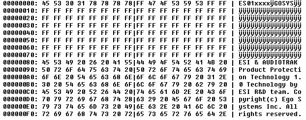
I publish below a screen copy of hexa content of each bad and good EEPROM,
for further reference and a link to get the bin file of the correct EEPROM.
I think this trick is intersting to know for all ESI juli@ owners.
Bad content:
Correct content:
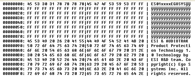
The bin file of good EEPROM is available at bottom of the post.
That end the ESI juli@ solved problem parenthesis.
Frex
As i said in my previous post, my ESI juli@'s are repaired by reprogramming the EEPROM.
(I also own now a RME HDSP 9632 that work fine too).
I publish below a screen copy of hexa content of each bad and good EEPROM,
for further reference and a link to get the bin file of the correct EEPROM.
I think this trick is intersting to know for all ESI juli@ owners.
Bad content:
Correct content:
The bin file of good EEPROM is available at bottom of the post.
That end the ESI juli@ solved problem parenthesis.
Frex
Attachments
Hello again,
The LTC2380-24 ADC project is still in progress.
I receive (normally) this week the FPGA EVM board to be connected
on the ADC board for receive data and made digital RIF filtering and more.
I get also a new enclosure to fit both cards together and add some buttons and connectors.
My last measurements done these days confirm the very good THD performance of the ADC.
I get THD at 1kHz with -1dBFS input signal better than -130dBc (FS equal 10Vpp).
Even at 10kHz and -1dBFS , ADC THD still below ppm level with all spurious below -125dB. I will post news soon.
Frex
With a cortex M-7 you could make a "web" based analyzer with no direct PC involvement. That would be really interesting. That part seems to have exceptional performance. If you are' processing it locally in the cortex then you need to do some significant translation to an audio compatible format for our familiar audio analysis stuff to use it.
LTC2380-24 ADC IMD and input noise tests
Hello all,
My FPGA EVM bard is not yet back in stock for delivery, and Mouser indicate me that
is due to USA bad weather...
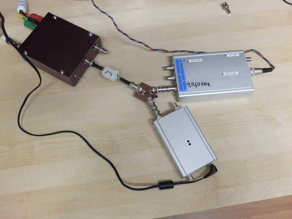
So, i decided to continue to make some measurements on the EVM : IMD and noise.
To do IMD measurements i have modified my EOSC10KV2 oscillator for 11kHz operation.
Then, i combine the signal with a second oscillator at 10kHz (The newer EOSC10KV3).
Both are added using resistive 600 resistive adder.
Each oscillators are set to deliver 2Vrms (5.66Vpp).
The RMS level seen by the ADC is about 1.4 Vrms(4Vpp).
Some pictures of the test setup:
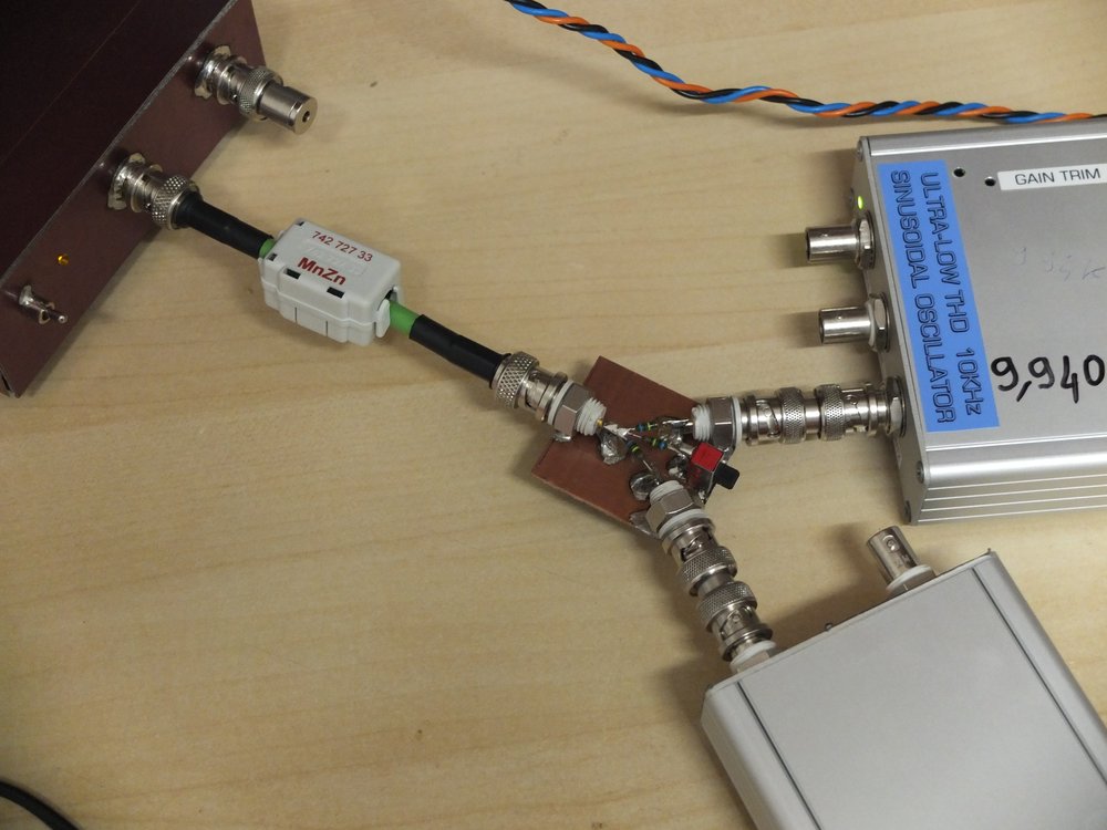
And the 10kHz-11kHz oscillators summing node:
The resulting IMD is show below :
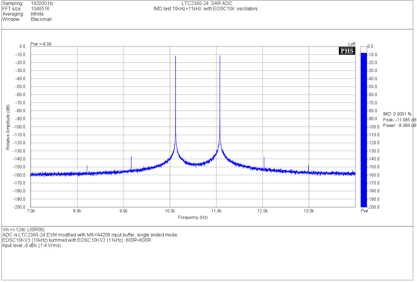
IMD products are all below -128dB from each oscillators signal.
After that, i wanted to know more about the input noise of the ADC
at different sampling rate (here, 48,96,192kHz).
Unfortunately, there is very few FFT software that allow sample histogram display,
that is probably one of the better figure for noise measurements.
(I know only Baudline allowing this, a very powerful FFT software for Linux).
So, i used another way. I done some recording at different sampling rates
to get the 24bits data in a wav files.
Then i made the computation with GNU Octave.
All measurements are done with 480k samples (10s for 48kHz) with the inputs
of ADC shorted with 50 Ohms plugs.
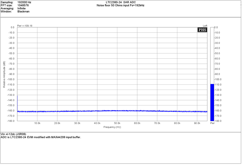
First, the FFT plot of each sampling rate :
Note that all FFT are referred to full scale level.
(0 dBFS = 10 Vpp = 3.53 Vrms = +11 dBV)
Fs= 48 kHz (LTC2380-24 averaging rate x32 - Fs= 1.536MHz).
Input noise level : -115.03 dBFS
Fs= 96 kHz (LTC2380-24 averaging rate x16 - Fs= 1.536MHz).
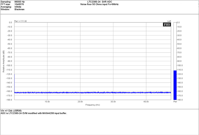
Input noise level : -111.93 dBFS
Fs= 192 kHz (LTC2380-24 averaging rate x8 - Fs= 1.536MHz).
Input noise level : -109.18 dBFS
As expected, the noise floor decrease of 3dB each time the averaging
ratio is multiply by 2.
The spectrum is very flat and doesn't show any residual spurious.
The last picture below is the result of the computation of the 480k samples
recorded in all sampling rate and passed thrue GNU Octave.
The vertical scale is normalized in percent of sample file, and the horizontal
scale show the number of sample for each ADC LSB bins.
For better clarity, the DC offset has been removed.
LTC2380-24 Noise distribution at 48-96 and 192kHz.
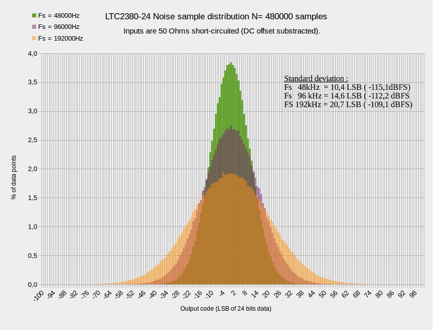
The graph show clearly a very Gaussian shape, sign of uncorrelated noise
and proof of clean PCB design. There is no sign of correlated signal that could
come from improper grounding, clock or others design issue.
The shape is narrowed as the averaging ratio increase.
The calculated standard deviation of each data gave same input level of FFT.
Seeing these results, I will add soon others sampling rate to allow more averaging
and so decrease again the noise floor.(of course at the expense of lower bandwidth).
I think also that making some digital filtering in FPGA will allow lower noise by
avoiding aliasing of out of band noise.
To be continued...
Frex
--------------------------------------------------------------------------------
JenSh,
For sure that could be great, but maybe that will change many things in your current design, no ?
TNT, I hope these picts will please you !
Lukaso,
The LTC2378-20 seem also very promising, and i have one in hand. I plane to try it also on the EVM board,
it's fully compatible with it. With a powerful uC as the Cortex M7 you will for sure make grate things...
Hello all,
My FPGA EVM bard is not yet back in stock for delivery, and Mouser indicate me that
is due to USA bad weather...
So, i decided to continue to make some measurements on the EVM : IMD and noise.
To do IMD measurements i have modified my EOSC10KV2 oscillator for 11kHz operation.
Then, i combine the signal with a second oscillator at 10kHz (The newer EOSC10KV3).
Both are added using resistive 600 resistive adder.
Each oscillators are set to deliver 2Vrms (5.66Vpp).
The RMS level seen by the ADC is about 1.4 Vrms(4Vpp).
Some pictures of the test setup:
And the 10kHz-11kHz oscillators summing node:
The resulting IMD is show below :
IMD products are all below -128dB from each oscillators signal.
After that, i wanted to know more about the input noise of the ADC
at different sampling rate (here, 48,96,192kHz).
Unfortunately, there is very few FFT software that allow sample histogram display,
that is probably one of the better figure for noise measurements.
(I know only Baudline allowing this, a very powerful FFT software for Linux).
So, i used another way. I done some recording at different sampling rates
to get the 24bits data in a wav files.
Then i made the computation with GNU Octave.
All measurements are done with 480k samples (10s for 48kHz) with the inputs
of ADC shorted with 50 Ohms plugs.
First, the FFT plot of each sampling rate :
Note that all FFT are referred to full scale level.
(0 dBFS = 10 Vpp = 3.53 Vrms = +11 dBV)
Fs= 48 kHz (LTC2380-24 averaging rate x32 - Fs= 1.536MHz).
Input noise level : -115.03 dBFS
Fs= 96 kHz (LTC2380-24 averaging rate x16 - Fs= 1.536MHz).
Input noise level : -111.93 dBFS
Fs= 192 kHz (LTC2380-24 averaging rate x8 - Fs= 1.536MHz).
Input noise level : -109.18 dBFS
As expected, the noise floor decrease of 3dB each time the averaging
ratio is multiply by 2.
The spectrum is very flat and doesn't show any residual spurious.
The last picture below is the result of the computation of the 480k samples
recorded in all sampling rate and passed thrue GNU Octave.
The vertical scale is normalized in percent of sample file, and the horizontal
scale show the number of sample for each ADC LSB bins.
For better clarity, the DC offset has been removed.
LTC2380-24 Noise distribution at 48-96 and 192kHz.
The graph show clearly a very Gaussian shape, sign of uncorrelated noise
and proof of clean PCB design. There is no sign of correlated signal that could
come from improper grounding, clock or others design issue.
The shape is narrowed as the averaging ratio increase.
The calculated standard deviation of each data gave same input level of FFT.
Seeing these results, I will add soon others sampling rate to allow more averaging
and so decrease again the noise floor.(of course at the expense of lower bandwidth).
I think also that making some digital filtering in FPGA will allow lower noise by
avoiding aliasing of out of band noise.
To be continued...
Frex
--------------------------------------------------------------------------------
JenSh,
For sure that could be great, but maybe that will change many things in your current design, no ?
TNT, I hope these picts will please you !
Lukaso,
The LTC2378-20 seem also very promising, and i have one in hand. I plane to try it also on the EVM board,
it's fully compatible with it. With a powerful uC as the Cortex M7 you will for sure make grate things...
Hello TNT,
As i wrote in my first post, i have modified the CPLD program on the LT EVM board to get directly
SPDIF output signal. Then, this new SPDIF output is connected to any SPDIF input of sound-card.
I personally use an ESI juli@ and a RME HDSP9632.
Both allow 192kHz input sampling rate on their SPDIF input.
So, i just need to use any recording application (like Audacity) to get wav file that content
digital data from the ADC (with 24 bits output data set).
On the EVM, the LTC2380-24 run at 1.536MSPS and perform 8x averaging
for 192kHz SPDIF sampling rate.
The ADC and oscillators are powered by +/- 12VDC JSR06 low noise PSU.
Frex
Frex: The noise measurements look quite good. One standard test is -60 dB THD+N to get a realistic picture of noise when signal is present. Its quoted as dynamic range on data sheets. It is a good way to unearth some "idle tones" and other artifacts that surface when the signal isn't static.
Are you running the chip at a high sample rate and averaging the samples down to audio rates? I think that's what I got reading through your notes.
Are you running the chip at a high sample rate and averaging the samples down to audio rates? I think that's what I got reading through your notes.
- Status
- This old topic is closed. If you want to reopen this topic, contact a moderator using the "Report Post" button.
- Home
- Design & Build
- Equipment & Tools
- SAR ADC for high performance audio ADC project [LTC2380-24]