Here's a schematic that might be useful -- from my archive. Unfortunately, I haven't always been good about noting sources. It might have appeared in one of those big Markus books.
It's from a 1960's era ARRL Handbook.
My "go to" HV variable supply is a variac driving a 650 VCT Chicago Transformer with a half-wave bridge and some 330u/400V caps series wired with parallel resistors for voltage leveling.
I have the Heath, Eico and Kepco HV supplies. The Kepco sits collecting dust, the Heath is in regular rotation and the Eico on a shelf looking pretty, but being somewhat noisier is less used than the Heath.
I built the "Art of Electronics" HV dual MOSFET supply -- using the innards of a Heath IP17. The control mosfet is driven by an AD825 and a 10-bit DAC. This was for my curve tracer article in AudioXpress more than a decade ago! Works really well, but for every day use the opamp/DAC could just be replace with a voltage source and potentiometer.
For some tube noise measurements I did (before Merlin's article was out) I series'd together a bunch of 9V cells from Radio Shack.
Less than a kilowatt
") Hello All,
Hello All,
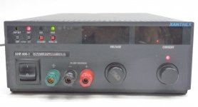
Today I received a package from the Keysight folks in Roseville, Ca. A “used”, looks like NOS not a mark and not a speck of dust, shiny Model N5752A 600 Volt DC by 1.3 Amp power supply. The enclosed original calibration certification is dated 26-Mar-2014.
This supplies less than a kilowatt, which is just fine for my expectations.
DT
Hello All,Today I received a package from the Keysight folks in Roseville, Ca. A “used”, looks like NOS not a mark and not a speck of dust, shiny Model N5752A 600 Volt DC by 1.3 Amp power supply. The enclosed original calibration certification is dated 26-Mar-2014.
This supplies less than a kilowatt, which is just fine for my expectations.
DT
Today I received a package from the Keysight folks in Roseville, Ca.
Hat tip to KEYS...the original HP. They have really done a great job keeping legacy manuals available for all us DIY types.
Hello smoking-amp and All,
PC curve tracer? Yes, sort of, kind of, digital curve tracer sort of as well, plus more.
I have been to a couple of Keysight Parametric Measurement Seminars at their Santa Clara campus. They have all the fun toys that measure and characterize the active devices of the world. All the technology and computers I wanted when I was a kid. For example:
http://www.keysight.com/upload/cmc_upload/All/Quick_IV_QSG_July_2013.pdf
I am no longer a kid, however I am getting some cool technology on my bench.
In addition to plotting tube data I am sorting out nonlinear functions, least sum curve fitting using the solver add-in to excel. Yes that nonlinear function is exactly the stuff of a precise spice model.
Check out this approach to Vacuum Tube modeling.
http://recherche.ircam.fr/pub/dafx11/Papers/76_e.pdf
With tube Parametric Data in hand we can place that tube in a real circuit to play with things like tuning / selecting the degree of cathode resistor negative feedback. Just the first item on a what if list.
I am deep into the LabVIEW chapter regarding exporting data to Excel.
It is going to be a while working out the process. First it will be testing and processing data for 2sk170’s using a $75, 15 volt Sorensen DC power supply. I do not want to inadvertently let the smoke out of that 600 volt 780 watt power supply.
This is all just for fun, I am sure much of this has been done before.
DT
Hat tip to KEYS...the original HP. They have really done a great job keeping legacy manuals available for all us DIY types.
jackinnj,
This power supply is current production.
Yes Keysight is awesome with all the manuals they keep posted on their sight.
DT.
soft start
Hello,
Over the past few days it has returned to winter here in northern California, cool wind and rain.
With the inspiration of this thread I have purchased a couple of Xanerex bench power supplies. Watching the outlets I found some good buys.
Not completed yet is computer controlled testing. On the breadboard is a 12AU7 , actually a 9AU7 wired up as a half mu circuit, the concept is to do FFT’s of this half mu and the grounded cathode version with the same voltage drop across the plate resistor of the grounded cathode circuit as across the top triode of the half mu. I wanted to verify voltages and operation of the DUT prior to connecting the audio analyzer.
To the point of this post; using a Xanerex XT 15-4 made it easy to dial in the 9.4V heater voltage at 0.22ma. The Xanerex XT 250-0.250 made it equally easy to dial in the B+ voltage exactly where I wanted it. The digital voltage and current displays are nice.
Talk about soft start; I set the maximum current of the XT 15-4 at 0.30 amps for the 9AU7 heater and set the voltage at 9.4 volts. I turned on the power supply, the output displays flashed about as the unit came to life. The current went to the maximum 0.30 amp value and the voltage slowly ramped up, over about 10 seconds, and stopped at 9.4V, as the voltage came up the current settled in at 0.22A. Soft and slow heater warm up I would say.
DT
I started a thread on use of the LTC LT3080 Floating regulator in an HV adjustable circuit:
http://www.diyaudio.com/forums/power-supplies/290753-lt3080-high-voltage-floating-regulator.html
The LT3080 is a single-pin adjust greatly simplifying design. Unlike a Maida, there is only 1mA flowing in the "adjust" circuit so you can use a much lower wattage potentiometer for adjustment.
http://www.diyaudio.com/forums/power-supplies/290753-lt3080-high-voltage-floating-regulator.html
The LT3080 is a single-pin adjust greatly simplifying design. Unlike a Maida, there is only 1mA flowing in the "adjust" circuit so you can use a much lower wattage potentiometer for adjustment.
I'm trying to fix a Xantrex XHR600-1.7 that just blinks (dimply) the displays on power up.
If it has the RS-232 or GPIB option board (M9B marked on back), un-plug the two ribbon cables inside going to that board.
Make sure it has the outside sense lines connected from the bigger J2 SNS- and SNS+ terminals to the smaller output connector SNS- and SNS+ (on back) respectively. No other jumpers should be connected on J2. (if so, record positions, then remove)
Switch SW1 on the back should have just positions 5 and 6 ON. Sometimes an inverted DIP switch may have been used that has ON and OFF flipped, so try the mirror image also. (can also check the DIP switch to see if its markings agree with the back panel markings)
On the PCR02-I control board inside, socket position J5 should have jumpers from 1 to 16, 2 to 15, 3 to 14, 4 to 13 and 5 to 12.
Bottom side, Main board: check the AUX power supply fuse in front corner near the two wire (red and blk wire) connector, 0.5 A 250V Fuse.
Make sure there is NO small plug in relay board (remote turn-on option) behind the front panel ON/OFF switch. IF so, remove, and re-attach Red and Black wires to power switch directly. Reds on one side of DPDT switch, and blacks on the other side.
When powered up initially, does the internal fan come up to speed?
Do any Red LEDs stay on, on any board or the front panel? Like OVP. Sense protect... Press the Standby button, then press to release. May free up a Standby condition. Make sure the Current Knob is set upward some, above 0, so that current limiting does not prevent output V from coming up.
J3 connector on main board (bottom side, just the solder pattern is visible near the small electrolytics. This is the AUX power supply connector to the control board back side. J3-pin 10 is AUX Gnd. J3-8 is +18V (unreg.) and J3-12 is -18V (unreg.) J3-6 is +5V. J3-1 and J3-2 are an isolated 9V (un-reg.) supply, J3-1 is the positive, J3-2 is the neg.
Be careful not to short any of these AUX power terminals while testing!!
In the PFC section between the two BIG 400V caps, there is a 6.3 Amp Fuse, F300, check this (while powered down!!)
There is a connector cable (Red/Blk wires) from near this fuse over to the earlier AUX power fuse: P301 to P2 This has about 312VDC on it when operating. This is the output of the PFC section. DO NOT SHORT while testing!! Can access back of Nylon connectors for pins. Red is +, BLK is -. Use EXTREME CAUTION!!!! while probing anything in this supply while powered up. HV 312V from PFC all around, and eventually 600+V near the output capacitors and xfmr section.
Any sign of work having been done on the supply? Any burned looking components? All ICs are in sockets typically, so one can re-seat these carefully (powered down, disconnected).
What controller IC is used in your model? Will either be a UC3524 chip on main board near the Mosfet row, or a small plug-in daughter board on the chassis edge with UC3875 chip. Make sure daughter board is plugged in fully and bolted with an insulator sheet between it and chassis.
Last edited:
Additional J3 terminals on main board, bottom connector solder pattern (signals from control board) (same conn. as AUX power):
J3-11 is Cntrl Gnd (0V reference), J3-13 is Cntl (-11.9V on working unit), J3-9 is S/D shutdown (-15V on working unit), J3-7 is OPTO RTN (-15V on working unit), J3-5 is AC FAIL (-9.1V on working unit)
Hopefully all this will help localize where the problem is.
One strange problem I saw once was the T2-AUXX-FMR xfmr in the AUX power section was not inserted fully into the main PC board. A corner pin had just a solder bridge connecting it to the main board, which had cracked. Re-soldering the pin from top xfmr side fixed it.
Make sure the current sensing resistor near the output connector is OK. (these blow out easily if the supply is shorted)
There is a small Mosfet on the heatsink near the output capacitors. This turns on whenever output voltage is above the V set point. Make sure it is not shorted from S to D.
Make sure the output capacitors are not shorted. Similarly any other big capacitors like PFC. (after allowing for the Powered-Down!! unit to fully discharge capacitors. Could use a shunting discharge resistor for safety.)
Could also check the various power Mosfets on the heatsink to make sure they are not shorted. (while Powered Down!!)
Last edited:
Sorensen usually has technical/service manuals available. Keep a watch for it.
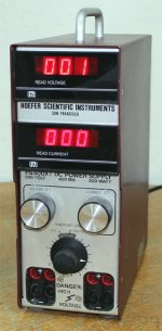
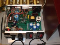
The 1 KW Lab bench supplies are nice for those mega-projects, but for the mundane stuff, I've found the Hoefer PS500XT power supply is real nice. 0-500V, 0-400 mA, 200 Watt, light weight. Often can find one for $100 with some patience. Takes up very little bench space. Does need an improved HF DC filter though, but easy to add. Try to find ones with a date code of '93 or above, early ones lacked a fan and over-heated.
The 1 KW Lab bench supplies are nice for those mega-projects, but for the mundane stuff, I've found the Hoefer PS500XT power supply is real nice. 0-500V, 0-400 mA, 200 Watt, light weight. Often can find one for $100 with some patience. Takes up very little bench space. Does need an improved HF DC filter though, but easy to add. Try to find ones with a date code of '93 or above, early ones lacked a fan and over-heated.
Attachments
Last edited:
Sorensen usually has technical/service manuals available. Keep a watch for it.
The 1 KW Lab bench supplies are nice for those mega-projects, but for the mundane stuff, I've found the Hoefer PS500XT power supply is real nice. 0-500V, 0-400 mA, 200 Watt, light weight. Often can find one for $100 with some patience. Takes up very little bench space. Does need an improved HF DC filter though, but easy to add. Try to find ones with a date code of '93 or above, early ones lacked a fan and over-heated.
Supplies like these are a dime a dozen in my industry. Seriously, we throw a ridiculous number in the "trash" (you don't want them, at my current work they are in BSL-2/3 labs). If you do purchase one of these supplies, there is a chance that they are contaminated (both with biologics and/or with salt). The buffers used in these reactions are usually moderate to high conc salt solutions. These get splashed everywhere and are a disaster waiting to happen. So when you receive one, open them up and thoroughly clean the insides. First with deionized water and then with 70% alcohol (the % is important here, no more-no less). These things are treated like rubbish and abused heavily, I don't want someone getting sick because some stupid lab didn't follow proper decon protocol.
(you don't want them, at my current work they are in BSL-2/3 labs). If you do purchase one of these supplies, there is a chance that they are contaminated (both with biologics and/or with salt). The buffers used in these reactions are usually moderate to high conc salt solutions. These get splashed everywhere and are a disaster waiting to happen.
Very interesting!!
In another thread on power supplies, I had mentioned the Biotech type Electrophoresis power supplies, such as the Hoefer unit above, with a question mark as to any hazards. One responder said these had to be thoroughly "cleaned" by any lab before they could be sold on Ebay. But while that may be proper procedure at many places, there are always going to be dumpster divers who pick them out of the trash and list them on Ebay.
I have alcohol washed any obvious splash or streaking from the units I purchased off Ebay. But looks like this should be more EMPHASIZED for these electrophoresis type supplies. Fortunately, the Hoefer unit does not have any vents on the sides or front, just bottom and back, where air exits through a fan. If the bench somehow got flooded with liquid I suppose the inlets on the bottom could suck in the mess. Front knobs would be an obvious site of contamination, and older units often have grimy knobs. Certainly clean those. Could replace knobs if too far gone.
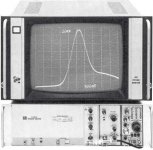
This brings back some memory of a Tektronix R7902 high speed storage scope I bought used (cheap) a long while back. The sellers said it had been used for recording single shot "nuclear events"!! Racks and racks of them for sale. I hadn't noticed any glow in the dark issues, but it is in storage now a long time. Still works good. Uses popular 7 series plug-ins, but came with a direct deflection plate access Vert. plug-in for BIG signals up to 1 GHz. They were like $20,000 new at the time, but I paid around $50 each for two of them. To think that they only got used for a single trace once! "Like new"
Last edited:
Correction: that was a Tek R7912 mentioned above, not R7902
Some info on the unusual Silicon Storage Target CRT "tube" it used:
154-0698-00, Tube 154-0698-00; Rohre 154-0698-00 ID42420
and the full transient digitizer:
Transient Digitizer R7912 Equipment Tektronix; Portland,
This thing put out a raster scan signal image of the storage target, and a GPIB digitized version to a minicomputer or PC. It didn't look too inviting to hobbiests without an obvious "CRT" so was a hard sell on the surplus market, but actually it was real easy to use with a monitor. Storage mode: 500 Mhz BW with a 7A19 Vertical plug-in, 750 Mhz with a 7A29 V plug-in, and 1 GHz with a direct access plug-in.
"In this Digital mode, the R7912 operates as an analog-to- digital converter with an effective clock rate of about 100 GHz." (this was back in 1973 !!)
.
Attachments
Last edited:
Still looking:
Make sure it has the outside sense lines connected
Sense lines are good.
Make sure there is NO small plug in relay board
Nope
When powered up initially, does the internal fan come up to speed?
Nope. The display LEDs blink dimly @ ~1Hz with numbers on them.
Do any Red LEDs stay on, on any board or the front panel? Like OVP. Sense protect... Press the Standby button, then press to release. May free up a Standby condition. Make sure the Current Knob is set upward some, above 0, so that current limiting does not prevent output V from coming up.
No change. No LEDs on.
J3 connector on main board (bottom side, just the solder pattern is visible near the small electrolytics. This is the AUX power supply connector to the control board back side. J3-pin 10 is AUX Gnd. J3-8 is +18V (unreg.) and J3-12 is -18V (unreg.) J3-6 is +5V. J3-1 and J3-2 are an isolated 9V (un-reg.) supply, J3-1 is the positive, J3-2 is the neg.
Be careful not to short any of these AUX power terminals while testing!!
All of these are toggling from zero to ~4vdc. Again, it looks like the LV supply is trying to come up and shutting back down. supply
In the PFC section between the two BIG 400V caps, there is a 6.3 Amp Fuse, F300, check this (while powered down!!)
Fuse good.
What controller IC is used in your model? Will either be a UC3524 chip on main board near the Mosfet row, or a small plug-in daughter board on the chassis edge with UC3875 chip. Make sure daughter board is plugged in fully and bolted with an insulator sheet between it and chassis.
U3524.
Short movie of the front panel blinking: http://www.fastbobs.com/movies/ps.mov
Make sure it has the outside sense lines connected
Switch SW1 on the back should have just positions 5 <deleted>
Just 5 & 6 on.
On the PCR02-I control board inside, socket position J5 should have jumpers from 1 to 16, 2 to 15, 3 to 14, 4 to 13 and 5 to 12.
Jumper is correct
Bottom side, Main board: check the AUX power supply fuse <deleted>
Fuses are good
Make sure there is NO small plug in relay board
When powered up initially, does the internal fan come up to speed?
Do any Red LEDs stay on, on any board or the front panel? Like OVP. Sense protect... Press the Standby button, then press to release. May free up a Standby condition. Make sure the Current Knob is set upward some, above 0, so that current limiting does not prevent output V from coming up.
J3 connector on main board (bottom side, just the solder pattern is visible near the small electrolytics. This is the AUX power supply connector to the control board back side. J3-pin 10 is AUX Gnd. J3-8 is +18V (unreg.) and J3-12 is -18V (unreg.) J3-6 is +5V. J3-1 and J3-2 are an isolated 9V (un-reg.) supply, J3-1 is the positive, J3-2 is the neg.
Be careful not to short any of these AUX power terminals while testing!!
In the PFC section between the two BIG 400V caps, there is a 6.3 Amp Fuse, F300, check this (while powered down!!)
There is a connector cable (Red/Blk wires) from near this fuse over to the earlier AUX power fuse: P301 to P2 This has about 312VDC on it when operating. This is the output of the PFC section. DO NOT SHORT while testing!! Can access back of Nylon connectors for pins. Red is +, BLK is -. Use EXTREME CAUTION!!!! while probing anything in this supply while powered up. HV 312V from PFC all around, and eventually 600+V near the output capacitors and xfmr section.
0V
Any sign of work having been done on the supply? Any burned looking components? All ICs are in sockets typically, so one can re-seat these carefully (powered down, disconnected).
Nope. Looks like new. All ICs re-seated.
What controller IC is used in your model? Will either be a UC3524 chip on main board near the Mosfet row, or a small plug-in daughter board on the chassis edge with UC3875 chip. Make sure daughter board is plugged in fully and bolted with an insulator sheet between it and chassis.
Short movie of the front panel blinking: http://www.fastbobs.com/movies/ps.mov
- Status
- This old topic is closed. If you want to reopen this topic, contact a moderator using the "Report Post" button.
- Home
- Design & Build
- Equipment & Tools
- Bench Supply