Hello UPD owners,
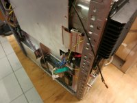
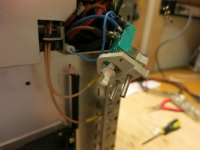
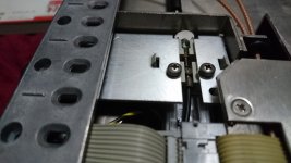
Some months ago I managed to get a broken UPD. I could fix it, but I have problems with the power switch, do not know how it is fixed in the case, it may be that something is missing, see the picture.
If someone could take off the bottom cover and send me a photo.
Thank you for your help!
Some months ago I managed to get a broken UPD. I could fix it, but I have problems with the power switch, do not know how it is fixed in the case, it may be that something is missing, see the picture.
If someone could take off the bottom cover and send me a photo.
Thank you for your help!
Attachments
I need advice to which instrument to buy upv, upd, upl or my be Sr1. I intend to use more or less exclusively for analog audio..like( Riaa, wow, distortion, fft and sooo on) and the spect are relatively similar.. I look more on upv due to newer hardware but upl more for price.
So what would be your recommendation?
So what would be your recommendation?
I need advice to which instrument to buy upv, upd, upl or my be Sr1. I intend to use more or less exclusively for analog audio..like( Riaa, wow, distortion, fft and sooo on) and the spect are relatively similar.. I look more on upv due to newer hardware but upl more for price.
So what would be your recommendation?
UPL is the best option, the UPD's are becoming more troublesome to keep going - the UPL is a newer design.
I have UPD's and UPV, and the UPV has a WORST noise performance then compared to the UPD/L it only achieves a lower noisefloor by using a higher FFT size... I guess they cheapened the analogue design.
For Wow and flutter you could also consider an AP1 if your on a budget - you could take the output from its notch filter section into a modern ADC for exceptional FFT results...
Well wow and flutter is just kompering.. I have seen sinjas post from measuring on flor noise.. Upl vs upv vs AP(I call it American ****-evel me") ) ok ok they are dam good machenes but still I will newer pay so much for external audio card.
) ok ok they are dam good machenes but still I will newer pay so much for external audio card.
So now I will see if upl or upd.. Depends on price.. No point to pay more for same performance.
But B1 option.. Im willing to clone original pcb.. Or it will came with machene or I will borrow from someone.
Thank you.
) ok ok they are dam good machenes but still I will newer pay so much for external audio card.So now I will see if upl or upd.. Depends on price.. No point to pay more for same performance.
But B1 option.. Im willing to clone original pcb.. Or it will came with machene or I will borrow from someone.
Thank you.
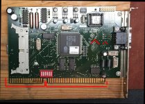
I do not own a UPD, but the Power switch here is just sticked into the Frontpanel. you see two "CLAWS" this one will have a counterpart either on the chassis or in the front panel.. I think more in the CHASSIS than in the Front Panel,. Check out the three holes in the front panel where and opposite of them you will find the slots to fix the PSU Switch.Hello UPD owners,
Some months ago I managed to get a broken UPD. I could fix it, but I have problems with the power switch, do not know how it is fixed in the case, it may be that something is missing, see the picture.
If someone could take off the bottom cover and send me a photo.
Thank you for your help!
Hope this helps
Regards
Chris
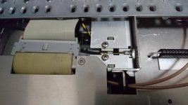
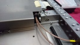
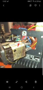
Im a proud owner of upd now. The device is working but after 20min started to smell magic smoke. OOOHH No.
After opening device the location of smell come from Power supply.
Furder inspection showed that electrolyte come from EMI filter.
I wrote to Rhode and Swartz directly and get without any problem user manuals.. But not service manuals.
Does anyone have service manual?
I need to see how looks power switch assembly
. The device is working but after 20min started to smell magic smoke. OOOHH No.After opening device the location of smell come from Power supply.
Furder inspection showed that electrolyte come from EMI filter.
I wrote to Rhode and Swartz directly and get without any problem user manuals.. But not service manuals.
Does anyone have service manual?
I need to see how looks power switch assembly
Attachments
Have you put the numbers on the Schaffner filter into Google? We found a replacement switch for our UPV that way.
Good luck with a service manual. My suspicion is that they are *highly* protected.
Ja ja no problem: FN378-4/21
If you can get your UPD to me I can work on it for you - I have 3 UPD's in the lab so easy to swap cards etc. to help locate the issue.
I've gained quite a bit of experience over the years keeping these units operational...
Well JohnW you are ekspert on upd's.. I have copied 8 .cal files from upd file.. And found 1 more in different file. Anyway how many cal files we are talking here?
I have some trouble to clone hhd... Still have 5.1 dos but upd is 3.1.. Cloning was attempted on kali. Will continue on other programs.
I have directly from R&s user files but you have service files.. Would love to get those if possible.
Im a proud owner of upd now
After opening device the location of smell come from Power supply.
Furder inspection showed that electrolyte come from EMI filter.
I wrote to Rhode and Swartz directly and get without any problem user manuals.. But not service manuals.
Does anyone have service manual?
I need to see how looks power switch assembly
Those line filters are known for failing like that. The issue comes up often on EEVblog forum.
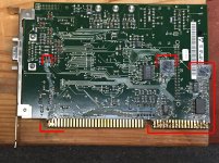
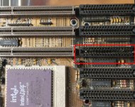
Pretty neat this thing is. I wasn't quite sure that I could get the sticky crap out
of the female contact area of the motherboard, Slot 3. Since slot 4 isn't used,
I figured I would desolder it and place it in Slot 3.
I'm glad I desoldered Slot 4 first because after my last post,
that is what I've been working on. it doesn't want to come out.
I think I'll work to get the sticky crap out of slot 3. It's nasty
adhesive and maybe some kind of derating stuff. It was placed
on a diaode pair and ran down the board also, into the female
connector.
It is what it is.
Cheers,
The battery on the DSP board retains calibration data and current setting but the calibration data is also stored in the HDD, according to this forum, so take care not to lose both of them!
I did not replace any caps yet, and also AC EMI filter. I will not do that until the UPD gets smoke.
I am not sure the gunk you wrote, but you can just put the video card on slot4, isn't it?
I did not replace any caps yet, and also AC EMI filter. I will not do that until the UPD gets smoke.
I am not sure the gunk you wrote, but you can just put the video card on slot4, isn't it?
Sinja, as_audio, electronic, thank you for the information.
I'm trying to find the 5V power lines that folks are talking about re-soldering.
Without power and without schematic it kind of tricky for me to ID, but I
assume it's likely the smaller 4 pin connectors on the motherboard and
similar low-voltage looking connectors to board interface.
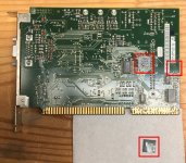
On the motherboard I de-soldered all of them cleaned up the board then
re-soldered.
I also cleaned up the area damaged by the 035 battery--the main mother board
socket and the smaller four pin socket perpendicular to the main socket by
removing them. Following that I cleaned out the green stuff, then gently
reflowed solder over the two damaged traces.
Measuring the traces with HP 34401A revealed same resistances as undamaged
traces throughout the repaired traces (from before repair start [the pulled mutha' board
connection], two places within the repaired trace, and at the end of the repaired trace)
all measured the same resistances.
Nuts, I guess I'm losing the cal data because the board is pulled and 3.6V long battery
is disconnected. It's still on the hard drive.
I've got pics in my iPhone, let me find it and post.
Cheers,
I'm trying to find the 5V power lines that folks are talking about re-soldering.
Without power and without schematic it kind of tricky for me to ID, but I
assume it's likely the smaller 4 pin connectors on the motherboard and
similar low-voltage looking connectors to board interface.
On the motherboard I de-soldered all of them cleaned up the board then
re-soldered.
I also cleaned up the area damaged by the 035 battery--the main mother board
socket and the smaller four pin socket perpendicular to the main socket by
removing them. Following that I cleaned out the green stuff, then gently
reflowed solder over the two damaged traces.
Measuring the traces with HP 34401A revealed same resistances as undamaged
traces throughout the repaired traces (from before repair start [the pulled mutha' board
connection], two places within the repaired trace, and at the end of the repaired trace)
all measured the same resistances.
Nuts, I guess I'm losing the cal data because the board is pulled and 3.6V long battery
is disconnected. It's still on the hard drive.
I've got pics in my iPhone, let me find it and post.
Cheers,
UPDate:
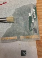
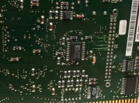
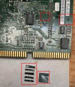
Here is the next batch of pics. It shows the Slot 3 VGA board
and the Grey Sludge on it. Then various pics removing and
cleaning the board with ISO, Bristle brush and KimWipes.
There is also MG "Q-tips" which I don't like that much.
I ran out of what I like (Bamboo Gun Swab "Q-tips)
because they are stronger and lint free..
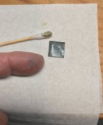
This grey sludge looks similar to arctic silver derating
grease. Why else the two black tabs coated with it and
why else the two diodes coated with it?
The stuff that ran down seems to be a combination
of the arctic silver and adhesive used to keep the black tabs in place.
Solder paste that was applied after production
run and someone forgot to remove it?
What say you?
It's 0 F* or -20 C*, (i.e., it's darn cold here in Texas.)
Cheers,
Here is the next batch of pics. It shows the Slot 3 VGA board
and the Grey Sludge on it. Then various pics removing and
cleaning the board with ISO, Bristle brush and KimWipes.
There is also MG "Q-tips" which I don't like that much.
I ran out of what I like (Bamboo Gun Swab "Q-tips)
because they are stronger and lint free..
This grey sludge looks similar to arctic silver derating
grease. Why else the two black tabs coated with it and
why else the two diodes coated with it?
The stuff that ran down seems to be a combination
of the arctic silver and adhesive used to keep the black tabs in place.
Solder paste that was applied after production
run and someone forgot to remove it?
What say you?
It's 0 F* or -20 C*, (i.e., it's darn cold here in Texas.)
Cheers,
Attachments
-
 02.01 rear Slot3 Zz Cleaning.jpg319.3 KB · Views: 96
 -
 02.01 rear Slot3 Z GreySludge.jpg403.7 KB · Views: 106
 -
 02.01 rear Slot3 Y removedTags.jpg336.4 KB · Views: 134
 -
 02.01 rear Slot3 X removed 2 Tags.jpg755.8 KB · Views: 137
 -
 02.01 rear Slot3 W removed tab1.jpg426.7 KB · Views: 143
 -
 02.01 rear Slot3 V GreySludge.jpg416.8 KB · Views: 138
 -
 02.01 Front Slot3 U GreySludge.jpg354.4 KB · Views: 150
 -
 02.02 Mutha board Slot3 SludgeDroppings..jpg448.7 KB · Views: 105
Are the motherboards and video cards standard cards? A PC motherboard is a really expensive thing to design so I would expect it to be a COTS board, same with video. If the OS is standard they they would not be trapped into maintaining those resources. Any other approach would be madness in product design.
- Home
- Design & Build
- Equipment & Tools
- Rohde & Schwarz UPD - HELP! Need docs, files & repair advice