From what I remember the post was for 4490 vs 4493 (https://www.diyaudio.com/forums/equ...er-ak5397-ak5394a-ak4490-288.html#post6027097)
My understanding from talking to the chip guys is that there is some internal tuning that relates to the sample rates. I was told they are optimized for the 44.1 family.
The 4493 was optimized for sound with some measurement compromises the designer said. The 4497 and 4499 are newer chips. The 4499 is focused on highest possible performance but with much more overhead in its implementation.
The 4493 was optimized for sound with some measurement compromises the designer said. The 4497 and 4499 are newer chips. The 4499 is focused on highest possible performance but with much more overhead in its implementation.
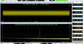
I found the part that causes the problematic THD btw channels and clock family.
Something goes wrong with the 5V reg (LT3042).
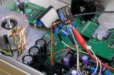
I isolated the LT3042 and fed the 5V from an external LT3042 with a very draft cabling.
As you can see there is no any problem, now.
I will search what is going wrong with on board LT3042 and I come back.
Something goes wrong with the 5V reg (LT3042).
I isolated the LT3042 and fed the 5V from an external LT3042 with a very draft cabling.
As you can see there is no any problem, now.
I will search what is going wrong with on board LT3042 and I come back.
Attachments

I found the part that causes the problematic THD btw channels and clock family.
Something goes wrong with the 5V reg (LT3042).
I isolated the LT3042 and fed the 5V from an external LT3042 with a very draft cabling.
As you can see there is no any problem, now.
I will search what is going wrong with on board LT3042 and I come back.
I see Power induced/related jitter signals... also seen on OPPO 205 with ESS9038Pro

Hp
It is indeed a strange problem.
But hasn't the external LT3042 just given you a high distortion on both channels instead of only one of them? In the old measurements you had a distortion of 0.00007% in some cases.
To the previous posts: Yes, I posted some comparisons of distortion with AK4490 and AK4493. As evident from the link, it was not compared to the AK4497 in that case.
But I did actually make a DAC board with the AK4497 back in 2016/2017. The initial results were a bit disappointing, when comparing to the AK4490 (using a 1 kHz signal at -20dBFS). But that was with the AK4490 using a 7 V supply, where I saw a very low distortion at -20dBFS. The RTX6001 use a 5 V supply for the AK4490 to give a better performance at higher levels, but sacrificing some performance at the low levels. The noise of the AK4497 was clearly lower, but at the time I didn't feel that the advantages of using the AK4497 instead of the AK4490 was worth the considerable cost difference.
But the result was not bad at all, and consistent on both channels as shown in the attached measurement. I can probably dig out the old PCB and do further measurements if needed.
Attachments
Thanks Jens, to participating...
Yes, with the on board LT3042 we have two issues in reality.
- the reversed THD btw the channels depending the clock family
- the bigger difference at the amount of THD, 0.00007% vs 0.00025% btw L/R
From what I have seen until now, with the on board LT3042, when the THD is lower to one channel, the other channel raise the THD, something like scale.
With the external LT3042 seems to work right, the THD is more balanced without significant differences (0.00031% vs 0.00029%) on 48K family and with some kind of difference with the 44.1K family clocks (0.00045% vs 0.00026%)
Yours capture has a very low THD and the two channels are almost identical. Can you give me the information, which 5V reg you used?
I think, the first that must I do, is to find the problem on board LT3042 and then to investigate some changing AK pins set again...
My suggestion (may be I'm wrong...)
The small inductance of the external draft cabling added to the circuit may be helps of minimizing the THD. You have to consider rearranging the components layout on your project pcb and may be add some inductance to the paths of LT3042.
...external LT3042 with a very draft cabling
The small inductance of the external draft cabling added to the circuit may be helps of minimizing the THD. You have to consider rearranging the components layout on your project pcb and may be add some inductance to the paths of LT3042.
I doubt that additional inductance will be a good thing.
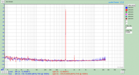
While the distortion figures have become more consistent between the two channels, they have also become worse for both channels and both sample rates! So the external supply only seems to make matters worse.
Could it be a layout related issue? Perhaps clock noise getting into the circuit?
I assume that the center pad of the IC has been grounded. But has it been soldered properly, under the IC?
Ghianni,
The output inductance of LT304x must be a lower (<2nH) according to datasheet.
Jens,
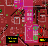
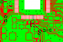
I am thinking, if the layout (mainly the inner vcc plane that I used for the output) is the cause. Tomorrow, I will put a second parallel cable from LT capacitor output to the (+) of first upper electrolytic capacitor.
For the mclk, see at the attachment the path and relation of this with the 5V power plane.
For the right soldering of plate...
I have same suspicious and I thought to resolder of the chip and solder again, but I have rise-up some pins of AK4497 for experiments and I am afraid that they are going to destroy with this resoldering (unfortunately I haven't a 2nd AK4497 for this).
The output inductance of LT304x must be a lower (<2nH) according to datasheet.
Jens,
I am thinking, if the layout (mainly the inner vcc plane that I used for the output) is the cause. Tomorrow, I will put a second parallel cable from LT capacitor output to the (+) of first upper electrolytic capacitor.
For the mclk, see at the attachment the path and relation of this with the 5V power plane.
For the right soldering of plate...
I have same suspicious and I thought to resolder of the chip and solder again, but I have rise-up some pins of AK4497 for experiments and I am afraid that they are going to destroy with this resoldering (unfortunately I haven't a 2nd AK4497 for this).
Attachments
It looks like your supply paths are rather long, with decoupling capacitors placed "far" away.
Furthermore, you have connected the AVDD and TVDD (pin 59 and 64) directly together. Apart from creating a potentially noisy coupling from digital to analog supply, it also blocks the ground connections from being connected under the IC. The AVSS on pin 60 goes a long way before being connected to anything.
I have attached a part of my layout to show how I did it.
Note that the decoupling capacitors are placed very close to the supply and ground pins. And the supplies for AVDD and TVDD are separated although they still come from the same regulator.
Multiple ground VIA's make sure that the ground on layer 1 is connected to an almost full ground plane on layer 2. An yes, it is only a 2-layer board.
I hope that the above can help you track down the cause of the problem. But there can of course be other areas, which have a greater impact on the performance.
Attachments
Thanks Jens for the really important notes about the layout.
I have a 4-layer setup, with a solid gnd plane on layer 2. The top layer includes except the parts and routes a gnd plane too.
I had a difficulty with the decoupling at the pins 49-64 of 4497, due the 0805 and CT3528 capacitor sizes.
I have see that you used 0603 size for this purpose.
Sure, all of these will include at the next pcb.
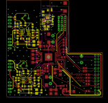
But, I have a curiosity about the reversed THD btw L/R and why this decreased with the external LT3042.
A mod that I have done on on board LT3042 (I joined with external cable the capacitor output with positive leg of the first electrolytic, it had no effect!
I have attached the eagle brd (I have removed a lot of layer details), it seems better now, how the LT3042 feeds the AK.
I have a 4-layer setup, with a solid gnd plane on layer 2. The top layer includes except the parts and routes a gnd plane too.
I had a difficulty with the decoupling at the pins 49-64 of 4497, due the 0805 and CT3528 capacitor sizes.
I have see that you used 0603 size for this purpose.
Sure, all of these will include at the next pcb.
But, I have a curiosity about the reversed THD btw L/R and why this decreased with the external LT3042.
A mod that I have done on on board LT3042 (I joined with external cable the capacitor output with positive leg of the first electrolytic, it had no effect!
I have attached the eagle brd (I have removed a lot of layer details), it seems better now, how the LT3042 feeds the AK.
Attachments
Maybe his experience is fitting your case here as well?
Final W-DAC 4493 development update – nihtila.com
Final W-DAC 4493 development update – nihtila.com
Thanks Joseph for the link.
I know that the LT304x doesn't need a large capacitance at the output and many times this is decreased performance of LT.
The AK in their datasheet suggests a large capacitance on Vref (470-2200uF) but I think this happens only with their reg that AK is using.
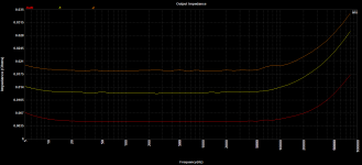
I have many times measure the output impedance of LT304x via the RTX, perhaps I must repeat this measurement to on board LT3042.
Another thought that I have in my mind, is to remove all the capacitors on 5V plane path and leeve only the 0.1 decoupling capacitors.
I know that the LT304x doesn't need a large capacitance at the output and many times this is decreased performance of LT.
The AK in their datasheet suggests a large capacitance on Vref (470-2200uF) but I think this happens only with their reg that AK is using.
I have many times measure the output impedance of LT304x via the RTX, perhaps I must repeat this measurement to on board LT3042.
Another thought that I have in my mind, is to remove all the capacitors on 5V plane path and leeve only the 0.1 decoupling capacitors.
Lemon,
May look at dimdim.gr with dual ak4493, anyway for a measurement system, with no channel crosstalk, a dual implementation is required. I see this also at the RME ADI2 Pro, as soon you use the dual DAC mode, channel crosstalk is gone.
In addition, the RTX project went to fast final run as putting things together, just look at how close is the transformer and in addition not shielded at all and turtles like to measure below 120 dB!!!???
A complete revamp is IMHO required otherwise fishing into the dark...
Hp
channel crosstalk
I really hope that someone (Manolis?) will build a similar upgrade for the RTX.
Cheers, E.
In addition, RME ADI2 Pro also uses two separate ADC chips. Now (that highly annoying) channel crosstalk between the inputs is gone as well plus a 3dB improved signal/noise ratio.Lemon,
May look at dimdim.gr with dual ak4493, anyway for a measurement system, with no channel crosstalk, a dual implementation is required. I see this also at the RME ADI2 Pro, as soon you use the dual DAC mode, channel crosstalk is gone.
[...]
Hp
I really hope that someone (Manolis?) will build a similar upgrade for the RTX.
Cheers, E.
Edward,
Only the RME ADI-2 Pro xxx has two ak4490/3 chips build in.
The ADC is an akm5574 in 2 (Stereo) x mono mode.
Adi-2 pro as RTX Do not have any un-balanced analog I/O. So measurement in this un-balanced connections will be a pitta. Also important would be a none coherent analoge I/O mode otherwise 2 HW gears are required.
Hp
Except that Dimitris (DimDim) is my friend, we collaborate to development some projects.
All the work with the dacs (that is uploaded to his blog) is familar to me.
The problem with the dual mono, for example for a 2x4493 is that needs a software mode implementation (register mode) and not hardware mode (pin mode) like Jen's dac happens.
For that reason, it is not enough to design a good dual mono pcb but it needs a completely redesign of analyzer with a controller inside.
The crosstalk of this analyzer is very good, from my measurement files, seem as Jen's DAC as mine 4497 is under -130dB.
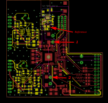
Before, I spent time to measure the Zo of the 4497 pcb at three points.
- a Reference point is the output capacitor of LT3042, it has 4.4miliOhms Zo almost.
- 1 is the first electrolytic capacitor, it has 13miliOhm Zo almost.
- 2 is the most away electrolytic capacitor on 5V plane, it has 18.5miliOhms Zo almost.
Except, that feeds me with what must change to next redesign pcb the results aren't bad to give an explenation for what is going wrong with the THD btw L/R channels.
All the work with the dacs (that is uploaded to his blog) is familar to me.
The problem with the dual mono, for example for a 2x4493 is that needs a software mode implementation (register mode) and not hardware mode (pin mode) like Jen's dac happens.
For that reason, it is not enough to design a good dual mono pcb but it needs a completely redesign of analyzer with a controller inside.
The crosstalk of this analyzer is very good, from my measurement files, seem as Jen's DAC as mine 4497 is under -130dB.
Before, I spent time to measure the Zo of the 4497 pcb at three points.
- a Reference point is the output capacitor of LT3042, it has 4.4miliOhms Zo almost.
- 1 is the first electrolytic capacitor, it has 13miliOhm Zo almost.
- 2 is the most away electrolytic capacitor on 5V plane, it has 18.5miliOhms Zo almost.
Except, that feeds me with what must change to next redesign pcb the results aren't bad to give an explenation for what is going wrong with the THD btw L/R channels.
Attachments
- Home
- Design & Build
- Equipment & Tools
- DIY Audio Analyzer with AK5397/AK5394A and AK4490