Conclusion: it is possible to get the same performance unbalanced as ballanced, with the not recommended unbalanced cabling topology, at least if you power the analyser from batteries.
Good work!
Would you care to share how the battery power was implemented on the RTX?
With a simple switch to change between grid and battery operation it sounds very attractive
")
I was still hoping for Jens and Jan to jump in and tell us how to do it with a couple of SilentSwitchers, but that would obviously also require some sort of battery so not really that different from your solution.
The setup is straight forward. I connect the PCB power connector to a switch with 2 positions and 6 decks. One position connects to the transformer. The other to three sets of batteries (external).
I use LiFePo4 cells (3.3V/cell). Six cells in series for each of the "15V"-rails and three cells in series for the "9V" rail.
Some elegant charging solution is still missing.
I use LiFePo4 cells (3.3V/cell). Six cells in series for each of the "15V"-rails and three cells in series for the "9V" rail.
Some elegant charging solution is still missing.

Before anyone thinks I only stubbornly refuse to choose the correct wiring for unbalanced measurement
The effect is, to a smaller extend, also present with the recommended "figure 17" wiring for unbalanced measurement.
Here a loopback with 0dBV in- and output setting
.jpg")
and with -20dBV in- and output setting.
.jpg")
I leave it to you to guess which color is line powered and which battery powered.
@NicMac: No I did no new current measurement, but I see no reason why it should have changed from the 0.3A on each rail with the SMPS.
The effect is, to a smaller extend, also present with the recommended "figure 17" wiring for unbalanced measurement.
Here a loopback with 0dBV in- and output setting
and with -20dBV in- and output setting.
I leave it to you to guess which color is line powered and which battery powered.
@NicMac: No I did no new current measurement, but I see no reason why it should have changed from the 0.3A on each rail with the SMPS.
@NicMac: No I did no new current measurement, but I see no reason why it should have changed from the 0.3A on each rail with the SMPS.
The 300 mA/rail is in the right ballpark. At least with light loads. With maximum output levels and outputs shorted, it will go to around 750 mA on the +19 V supply and around 600 mA on the -19 V supply. This is of course an extreme situation, but the built-in supply has been designed for this condition.
...First (red) the line power connected to the analyser and the transformer is line powered, but not connected to the analyser PCB. Second (green) line power unplugged.
You see, there is no difference. An indication that the transformer stray might not be the problem ... but keep in mind the transformer is driving no load here.
If there is no load on the transformer, there will be (almost) no current flowing through the trasformer, so stray fields would be expected to be much less. Could you repeat this test with a dummy load on the transformer to mimick the current flow as it would be if the transformer was powering the RTX6001?
If there is no load on the transformer, there will be (almost) no current flowing through the trasformer, so stray fields would be expected to be much less. Could you repeat this test with a dummy load on the transformer to mimick the current flow as it would be if the transformer was powering the RTX6001?
Well, yes I can do that but there will be some delay as I have no suitable load laying around.
But, if I see it correctly, at least with an ideal transformer the field should not change. The field induced by the (loaded) secondary side is inverse to that of the primary side - the whole energy transfer is just based on the "attempt" to keep the total field constant.
But we are in the real world so lets see what happens.
I made a measurement of the stray magnetic field to check the difference between the loaded and the unloaded transformer, see attached.
The loaded transformer clearly generates a lot more harmonics. I big part of that is probably caused by the non-linear load on the transformer (rectifiers and capacitors).
The difference is around 30dB. The 50 Hz fundamental does not change much, perhaps around 6dB.
The loaded transformer clearly generates a lot more harmonics. I big part of that is probably caused by the non-linear load on the transformer (rectifiers and capacitors).
The difference is around 30dB. The 50 Hz fundamental does not change much, perhaps around 6dB.
Attachments
Good point, rectifiers and reservoir caps should be part of the substitute load to make it somehow a simulation of the real thing.
I had earlier a post, DIY Audio Analyzer with AK5397/AK5394A and AK4490 , with the analyzer powered by the transformer moved about 30cm out of the case with an extension cable. There was still line artifacts in the measurement. So the stray field is surely not the only cause, but it might be interesting to see its influence isolated.
I had earlier a post, DIY Audio Analyzer with AK5397/AK5394A and AK4490 , with the analyzer powered by the transformer moved about 30cm out of the case with an extension cable. There was still line artifacts in the measurement. So the stray field is surely not the only cause, but it might be interesting to see its influence isolated.
I made a measurement of the stray magnetic field to check the difference between the loaded and the unloaded transformer, see attached.
The loaded transformer clearly generates a lot more harmonics. I big part of that is probably caused by the non-linear load on the transformer (rectifiers and capacitors).
The difference is around 30dB. The 50 Hz fundamental does not change much, perhaps around 6dB.
My one cent : it may worth trying a snubber to help reduce radiation when transformer is loaded. ie. a Quasimodo snubber
30 cm may not be nearly enough to get out of the field of the transformer. I could measure a significant field at the front of the box, but for perspective thats with 125V in on a 120V setting. A magnetic shield, even a steel strap will lower the field. The best solution is to reduce the internal flux in the transformer but that usually becomes a larger transformer for the same power. A snubber may reduce the higher harmonics but not the fundamental field.
A snubber may reduce the higher harmonics but not the fundamental field.
It would suppress the 100 Hz (120 Hz) harmonics and higher. But I'd be surprised if Jens did not include any snubbers in the design. Jens?
I haven't used a snubber, only capacitors across the rectifier inputs. But I don't see any ringing either.
I agree with Demian, a snubber would not reduce the fundamental field or the lower harmonics (3, 5, 7 etc.), which are the ones observed in measurements.
While the ringing pulses itself are high frequency, they occur 100 times (120 times) per second. This is 2nd order harmonics of 50 Hz (60 Hz). But if the pulses do not exist anyway, there's no point in digging deeper with the snubbers.
If moving the transformer 30cm away does not change much, what is causing the fundamental at 50 Hz (60 Hz)?
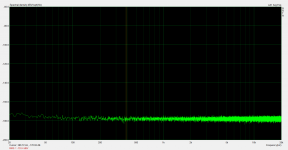
This is what I have (-20dBV input) if the transformer is moved 1.2 meter away.
Seems like you solved the issue without reinventing the PSU!
This is what I have (-20dBV input) if the transformer is moved 1.2 meter away.
Brutal!! ☺😊
Are You sure it's not a digital loopback ?! 😈
Joking!
- Home
- Design & Build
- Equipment & Tools
- DIY Audio Analyzer with AK5397/AK5394A and AK4490