not in front of the machine now, but I have a feeling mine might have came with this mod. I will check when I open it up again. One unit does not have the overload issue and one does.Please take a look at the document provided here:
GB for RTX6001 Audio Analyzer with AK5394A and AK4490
Right, your units were actually modified, concerning the overvoltage, before shipping. I just looked it up.
Perhaps you could take a look inside and check the modification on the bad unit? It might be possible to fix it easily, so that you don't have to send it back to RTX.
Perhaps you could take a look inside and check the modification on the bad unit? It might be possible to fix it easily, so that you don't have to send it back to RTX.
Again annoyed by the 50Hz power-line induced artefacts in unballanced measurements using a BNC-XLR adapter (or even, to a little extend, with the recommend "no.xx" cable layout) I decided to test what would happen when the RTX is supplied with power that has "no" 50Hz content.
The following was just intended as a proof of concept with the material lying around, so far far from an optimal solution. I used 3 switched mode Laptop/Computer power supplies followed by a linear regulator to get the suitable voltage.
As the power supplies are not synced and different there is unnecessary HF noise.
The regulators were of LM317 type, thus not intended for switched mode supplies (no good HF rejection).
This causes a few spikes around 70kHz which show also up in the measurements and can be avoided with a descent supply-regulation approach.
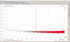
First, as indication that there is no performance loss due to the SMPS, a balanced loopback measurement, a 1kHz test signal at -12dB (settings 0dBV out, -10dbV in). Green the original supply, red the SMPS:

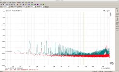
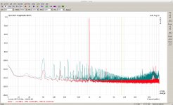
Then a unballanced loopback: BNC out to BNC cable to commercial BNC-XLR adapter. The BNC cable was not the best performing I had, but for a test this might be an advantage. First the noise floor, second a 1kHz test signal at -6dB (settings 0dBV out, -10dbV in). Green the original supply, red the SMPS:


Conclusion, I would say, there is room for improvement, at least for the measurement ease of the user, in for unballanced measurements.
P.S. I give intentionally not more details on the SMPS setup as you should not duplicate it unless you know very well what you do. You can easily damage your analyzer and, of cause, warranty is voided by the attempt.
The following was just intended as a proof of concept with the material lying around, so far far from an optimal solution. I used 3 switched mode Laptop/Computer power supplies followed by a linear regulator to get the suitable voltage.
As the power supplies are not synced and different there is unnecessary HF noise.
The regulators were of LM317 type, thus not intended for switched mode supplies (no good HF rejection).
This causes a few spikes around 70kHz which show also up in the measurements and can be avoided with a descent supply-regulation approach.
First, as indication that there is no performance loss due to the SMPS, a balanced loopback measurement, a 1kHz test signal at -12dB (settings 0dBV out, -10dbV in). Green the original supply, red the SMPS:

Then a unballanced loopback: BNC out to BNC cable to commercial BNC-XLR adapter. The BNC cable was not the best performing I had, but for a test this might be an advantage. First the noise floor, second a 1kHz test signal at -6dB (settings 0dBV out, -10dbV in). Green the original supply, red the SMPS:


Conclusion, I would say, there is room for improvement, at least for the measurement ease of the user, in for unballanced measurements.
P.S. I give intentionally not more details on the SMPS setup as you should not duplicate it unless you know very well what you do. You can easily damage your analyzer and, of cause, warranty is voided by the attempt.
Again annoyed by the 50Hz power-line induced artefacts in unballanced measurements using a BNC-XLR adapter (or even, to a little extend, with the recommend "no.xx" cable layout) I decided to test what would happen when the RTX is supplied with power that has "no" 50Hz content.
The following was just intended as a proof of concept with the material lying around, so far far from an optimal solution. I used 3 switched mode Laptop/Computer power supplies followed by a linear regulator to get the suitable voltage.
As the power supplies are not synced and different there is unnecessary HF noise.
The regulators were of LM317 type, thus not intended for switched mode supplies (no good HF rejection).
This causes a few spikes around 70kHz which show also up in the measurements and can be avoided with a descent supply-regulation approach.
First, as indication that there is no performance loss due to the SMPS, a balanced loopback measurement, a 1kHz test signal at -12dB (settings 0dBV out, -10dbV in). Green the original supply, red the SMPS:
View attachment 704727
Then a unballanced loopback: BNC out to BNC cable to commercial BNC-XLR adapter. The BNC cable was not the best performing I had, but for a test this might be an advantage. First the noise floor, second a 1kHz test signal at -6dB (settings 0dBV out, -10dbV in). Green the original supply, red the SMPS:
View attachment 704728 View attachment 704729
Conclusion, I would say, there is room for improvement, at least for the measurement ease of the user, in for unballanced measurements.
P.S. I give intentionally not more details on the SMPS setup as you should not duplicate it unless you know very well what you do. You can easily damage your analyzer and, of cause, warranty is voided by the attempt.
Good stuff!
I don't really know your external PSU setup, and which RTX internal sections you "skipped", but... would it make sense to think about a mod for an external DC PSU to keep the mains noise out of the RTX?
Good stuff!
I don't really know your external PSU setup, and which RTX internal sections you "skipped", but... would it make sense to think about a mod for an external DC PSU to keep the mains noise out of the RTX?
I only skipped the transformer inside the RTX and used the corresponding connector as power input. Minimal invasive, but perhaps not optimal
I do not think an external supply will noticeably improve the balanced performance. But unbalanced live would become easier.
I think about battery power the RTX, but that would need a lot of batteries.
I think about battery power the RTX, but that would need a lot of batteries.
What voltage is required?
Using an external transformer would bring only a minimal improvement - if any at all.
No, not just an external transformer, but a whole DC PSU.
I think about battery power the RTX, but that would need a lot of batteries.
Can't be that many batteries. Getting it completely of the grid is tempting
Did you by chance check the voltages and current draw on the different secondaries?
The internal transformer is 1 x 9V and 2 x 15V, 1A (AC).
A drop in DC replacement for the transformer would thus be about 1 x 12V and 2 x 21V. The margin above the voltage drop of the regulation circuitry however seems to be quite ample. Slightly less would probably do too.
I do not think it would be a good idea to bypass the internal regulation and feed the power rails directly (I have even not yet made an attempt to identify all rails). If that would be wanted then better put that on the RTX-v2 wish list with a newly designed PCB.
Your experiment clearly show a benefit even without bypassing the internal regulation so I would leave it as it is for safety and simplicity.I do not think it would be a good idea to bypass the internal regulation and feed the power rails directly (I have even not yet made an attempt to identify all rails). If that would be wanted then better put that on the RTX-v2 wish list with a newly designed PCB.
Could you possibly record the current drawn by the 3 SMPS you are using to get an idea of how much current the analyser actually draw?
A battery solution that only last 30 minutes is not really practical for anything else than proof of concept
Hi mbrennwa,
I guess I have more confidence in the design abilities that Jens has. It would be so easy to create worse performance compared to what it has now.
I generally ignore the 60 Hz (here) performance and look at the 120 Hz noise for clues having to do with power supply performance of the DUT.
-Chris
I guess I have more confidence in the design abilities that Jens has. It would be so easy to create worse performance compared to what it has now.
I generally ignore the 60 Hz (here) performance and look at the 120 Hz noise for clues having to do with power supply performance of the DUT.
-Chris
...
Could you possibly record the current drawn by the 3 SMPS you are using to get an idea of how much current the analyser actually draw? ...
The 12V and one of the 21V lines draw slightly less than 0.3A. The other 21V line 0.3A or very slightly above.
Right, your units were actually modified, concerning the overvoltage, before shipping. I just looked it up.
Perhaps you could take a look inside and check the modification on the bad unit? It might be possible to fix it easily, so that you don't have to send it back to RTX.
Discovered the over voltage occurs when the USB cable is connected. What does this mean?
The RTX has its chassis connected to the power ground which could be the source of the noise. The transformer radiation is higher than I would have liked to see and that may be the biggest cause of the power line noise. I'm running 125V AC here on the 120V setting and the magnetic field is high but manageable. Its not from ripple on the supply. There may also be some capacitive leakage from the transformer to the chassis causing currents in unwanted places.
How is the "commercial" BNC to XLR adapter wired? Most I have seen are wired for maximum hum pickup. I would use the input differentially with a separate wire from pin 1 back to the DUT or source. Any other connection will be something of a performance compromise.
Personally I have no issues with using a good SMPS for this but would not want to hassle designing one. Getting a single multi-output supply with the necessary outputs and autoswitching may be difficult for a run of 100 units.
Discovered the over voltage occurs when the USB cable is connected. What does this mean?
Did you modify this RTX with a S/PDIF output? Does the USB connector touch the chassis?
- Home
- Design & Build
- Equipment & Tools
- DIY Audio Analyzer with AK5397/AK5394A and AK4490