The challenge of autoranging in this application comes from several factors. On a traditional analyzer the autoranging has a wide range and fine steps. The Shibasoku 725 adjusts in 2.5 dB steps with a jillion relays. This is typical to keep the signal at the optimum for the system. That doesn't really work for DAC/ADC systems. First the optimum for distortion is different from optimum for SNR. Second, in the case of the RTX the steps are pretty coarse. Finer steps would be nice but quite expensive to implement and bring possible confusion.
The Liberty Praxis does address this with a digital pot in the audio interface under program control. Bill Waslo has an auto adjust routine to optimize the input signal using the pot so the display is always calibrated at at an optimum level.
My suggestion would be like this-
For level and SNR measurements switch the source at -3 dBFS up and - 23 dBFS down.
Switch the analyzer at -3 dBFS going up and -13 dBFS going down (Keep the signal no higher that - 3dBFS, except for high crest factor signals then this needs to be different. . .)
For distortion keep the source and input between -15 dBFS and -25 dBFS for the lowest distortion.
Ok, I see... thinking a bit more about how this would work in the MATAA environment it gets hairy quickly. MATAA is not about "level and SNR measurements" or "distortion measurements". The sound I/O in MATAA is just that, a tool that sends a test signal to the DUT and records the response. The analysis of these data in terms of distortion, levels, noise, or whatever the uses has programmed in his analysis procedures is totally decoupled from the audio in/out. Assuming anything about the type of test or analysis going on will limit the flexiblity of MATAA. I guess I might just think about autoranging a bit more.
For me just reading back the actual level to scale displays would be enough value. Especially showing level and dBFS at the same time would help get the best readings.
One thing I like about DiAna is seeing the waveform, the recovered distortion waveform and the distortion spectrum at the same time. Seeing the waveform during setup helps prevent unnecessary mistakes with levels and clipping.
That's a good point. I also often plot the time-domain signal for the same purposes. Autoscaling it is!
Now I have to figure out some glitches with USB communication to the RTX.
Things seem to go smooth as long the overflow (or overvoltage) indicators remain off. Once they go on, the RTX seems to swamp the USB buffers with repeated overflow (or overvoltage) messages, which seem to get in the way with reading the switch status information.
Also, the overflow + overvoltage information I am getting via USB seem to be different than the LED indicators on the front panel. Urgh.
Ok, I think I've got this under control now. I worked a bit on the MATAA side of things and now have something that seems to work on my Linux computer with GNU Octave. I will also test with Octave on my Mac. However, I don't have Matlab or Windows. If anyone would like to run a few tests on Matlab or Windows, please let me know.
Important pricing change for RTX6001 owners concerning MI Pro GB please see: GB for Virtins MI Pro for RTX6001 autoranging/autoscaling & for soundcard end users - Page 15 - diyAudio
I think there are at least two distinct cases for autorange. On the ADC side- First for response/SNR where the level should be between -3 and -10 dBFS to get max SNR. The second case is for linearity or distortion measurements the optimum on the input is between -15 dBFS and -20 dBFS. The ADC is similar but the 20 dB steps is more constraining.
This suggests the ranging should be selected as a function of the testing. And typically you may need a manual override.
This makes some sense in light of the system limitations. Even traditional analog analyzers have similar limitations.
This suggests the ranging should be selected as a function of the testing. And typically you may need a manual override.
This makes some sense in light of the system limitations. Even traditional analog analyzers have similar limitations.
I couldn't agree more, except that I think there may be more than just two distinct cases, depending on the software / tools you're using. For a software tool that accomplishes a very specific test, it may be straightforward enough to define the "rules" for autoranging with the RTX6001. With more flexible software tools it seems to me it would be better to do no autoranging at all and leave the range selection to the user. That's how I implemented the RTX6001 integration in MATAA.
How many HW mods are there for the Jensalyser ???
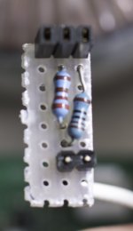
I have the "over voltage control circuit" kit and the "shields, capacitors and resistor" kit.
I read about the SPDIF fix in this thread, but are there more I have missed ???
Life have kept me rather busy so I have not applied any of the kits yet.
I have the "over voltage control circuit" kit and the "shields, capacitors and resistor" kit.
I read about the SPDIF fix in this thread, but are there more I have missed ???
Life have kept me rather busy so I have not applied any of the kits yet.
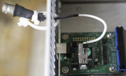
Good to know but I rather drill a hole in the back and make the connector permanent.
Is the previously mentioned pulse transformer needed ???
Good to know but I rather drill a hole in the back and make the connector permanent.
Is the previously mentioned pulse transformer needed ???
In my case, I have already one on the receiving side, so I didn't bother.
As you need to unscrew the back plate (at least to a certain extend) to open the case, some flexibility, somewhere, is needed.
PS. I have put the capacitor from the schematics, it is a tiny SMD.
- Home
- Design & Build
- Equipment & Tools
- DIY Audio Analyzer with AK5397/AK5394A and AK4490


