Isn't it local pickup only?
It was, but the seller told me it was an error and he'd be glad to ship, but fussed that he didn't know how to set a reserve price on an auction. Apparently he got concerned I'd win it at a much lower price than the $600 buy it now price and magically I get an eBay email stating the auction had been cancelled.
The tools Duke has given me are invaluable nevertheless, particularly in regard to measurement techniques for performance verification. I've been fooling around with a circuit design for a month or so and should have it completed in another month. It includes ideas from Chris Strahm's LF280 as well as the AP unit. At least now I have solid methods to figure out how bad I fail at it.


Hi Bane
It look like you have a good start on the filter. Can you run an ANALOG frequency response with and without the filter only using the Dscope? One of the HF spikes is not attenuated. What about checking the differential mode? What is the distortion of the filter? How much change in the distortion of the amplifier with & without the filter?
Send me a message or call as I can help you set up some tests. You may be able to make some improvements.
Duke
Hi Bane
It look like you have a good start on the filter. Can you run an ANALOG frequency response with and without the filter only using the Dscope? One of the HF spikes is not attenuated. What about checking the differential mode? What is the distortion of the filter? How much change in the distortion of the amplifier with & without the filter?
Send me a message or call as I can help you set up some tests. You may be able to make some improvements.
Duke
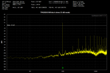
Hi Duke, appreciate the help. Pics below. Freq response, common mode response, and thdn with two different values for lpf 22k and 40k (hpf was 22hz). Last is full shot of freq response.
I can't remember how large of a thdn difference it made with the classD amp, it was fairly significant.
Thanks,
Ben


Some brief notes on measuring class D: The big class D amps with hefty output filters can usually be measured as-is directly into the analyzer. They are required to have really good LC output filters because these amps must be designed to drive various types of tweeters, and tweeters don't usually have enough inductance to filter the switching. And so, if you don't have a solid LC filter and drive a tweeter, the tweeter is probably ruined.
Note these big amps generate a 0V signal by "pushing" the +V rail and the "pulling" the -V rail. Even though the output is zero, the amp is still slamming the signal rail to rail on each switching cycle. That is heavily filtered, resulting in a zero.
These big class D amps also have to meet EMI, which means they cannot have high slew rate signals existing on a wire going to a speaker. Again, this means great LC output filter.
In the end, these types of amps can usually go straight into an audio analyzer (differential, of course).
There's another type of class D amplifier called "filterless". These are usually small, few watt amps where the amp is married to the speaker by the equipment maker (think of cell phone) and the speaker is very inductive by design.
These amps generate a 0V signal across by pushing the same switching signal (no phase shift) to both terminals of the speaker. They do it this way because these are usually supply amps. To generate a non-zero signal, they simply slide one of the output switching waveforms in time. Very clever. The fidelity on these amps isn't great. But the other wins are huge.
If you put the output of these amps directly into an analyzer, the slew rates cause big problems. But it's easy to fix: just run the amp output through the TI-recommended first-order 30 KHz RC filter posted earlier in the thread. That it! That filter smears the fast edges of the switching signal just enough so that the CMRR of the analyzer can take care of the rest.
Here's a capture of a TI TPA2038 filterless class D. It's rated for 1% at 2.5W into 4 ohms from 5V, and the measurement confirms that. This was using TI's prescribed first order RC filter.
Attachments
Some brief notes on measuring class D: The big class D amps with hefty output filters can usually be measured as-is directly into the analyzer. They are required to have really good LC output filters because these amps must be designed to drive various types of tweeters, and tweeters don't usually have enough inductance to filter the switching. And so, if you don't have a solid LC filter and drive a tweeter, the tweeter is probably ruined.
Note these big amps generate a 0V signal by "pushing" the +V rail and the "pulling" the -V rail. Even though the output is zero, the amp is still slamming the signal rail to rail on each switching cycle. That is heavily filtered, resulting in a zero.
These big class D amps also have to meet EMI, which means they cannot have high slew rate signals existing on a wire going to a speaker. Again, this means great LC output filter.
In the end, these types of amps can usually go straight into an audio analyzer (differential, of course).
There's another type of class D amplifier called "filterless". These are usually small, few watt amps where the amp is married to the speaker by the equipment maker (think of cell phone) and the speaker is very inductive by design.
These amps generate a 0V signal across by pushing the same switching signal (no phase shift) to both terminals of the speaker. They do it this way because these are usually supply amps. To generate a non-zero signal, they simply slide one of the output switching waveforms in time. Very clever. The fidelity on these amps isn't great. But the other wins are huge.
If you put the output of these amps directly into an analyzer, the slew rates cause big problems. But it's easy to fix: just run the amp output through the TI-recommended first-order 30 KHz RC filter posted earlier in the thread. That it! That filter smears the fast edges of the switching signal just enough so that the CMRR of the analyzer can take care of the rest.
Here's a capture of a TI TPA2038 filterless class D. It's rated for 1% at 2.5W into 4 ohms from 5V, and the measurement confirms that. This was using TI's prescribed first order RC filter.
Not sure I'm totally on board. Every mobile audio Class-D i've run on a dscope has had decent output filters built in. See post 62. All have had problems with aliasing crap into the 20-20khz range from higher up.
Begs the question, is rolling off the top with an aux-0025 (or the like) a fair way to measure thd... In my mind, that stuff isn't really there and is analyzer error but.... hmm
It's easy to check: Just make the measurement with and without filters as you did. If there's a difference, then that's your answer! I guess my point was more along the lines of there's 2 types of class D, one type (filterless) definitely needs an external first-order filter always and the other type (filtered) often not.
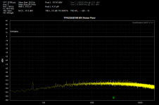
Here's a TI 300W class amp (no input) running at 50V rails straight in with no filters. 91 uV of noise A weighted, 20 to 20 KHz. TI typical spec is 85uV.
Yes, I think AUX-0025 is fair for measuring THD. TI specs their THD measurements with 80 to 80 KHz bandwidth specified on the analyzer BUT with an AUX-0025 and an AES17. So, effectively a brick-wall beyond 20 KHz.
Attachments
Note: The AUX-0025 filter is not a BRICK WALL FILTER
Duke
The AES17 gives 60 dB of rolloff from 20 to 24KHz. That's certainly seems like a brick wall filter.
The AES17 gives 60 dB of rolloff from 20 to 24KHz. That's certainly seems like a brick wall filter.
That's in software, doesnt help here..... analyzer front end slew induced errors and aliasing wont be fixed by rolling off the upper response in software.
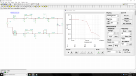
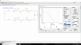
Still picking up some major hash in 50k region with some class D amplifiers at test. Think I'm going to rework my filter to below. First pic is the aux_0025 setup, 2nd is what I'm thinking.
Took a lot of guess and check (as i'm no filter expert lol), good chance i'm overlooking something like over-loading one of my newer low-value resistor choices. Guess we'll see
Down a bit more than half db at 20k.. not too concerned with that, tried to get the best roll-off i could from 20k-100k without a total gut job.
Attachments
Last edited:
Hi bnae38
The AUX0025 filter is used to stop the MEASURING ANALYZER from overload/slewing/creating distortion products. The AP’s have a 500 KHz plus analog BW and some HF noise or carrier could cause some form of IMD. The output filter on the Class D amp or design is needed to reduce the carrier output.
The speaker cable is an antenna that radiates the carrier to the world.
Modifying the filter does not make the amplifier any better.
Duke.
That's in software, doesnt help here..... analyzer front end slew induced errors and aliasing wont be fixed by rolling off the upper response in software.
The filter can be either. The S-AES17 filter for AP is a hardware filter. National Instruments offers a software version of the filter.
The hardware filter will of course solve the slew-induced error problem. The software filter won't.
The filter can be either. The S-AES17 filter for AP is a hardware filter. National Instruments offers a software version of the filter.
The hardware filter will of course solve the slew-induced error problem. The software filter won't.
I saw that the other day
, sorry for my response awhile back you bring up a good point.I have a Prism Sound setup however, so not an option here. That and I'd rather DIY it anyway
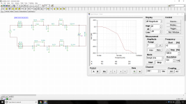
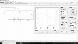
.Anyway, my train of thought could be off base here.. but thinking i'm going to go for this. Is a more stout filter after 20k. May just fubar my phase response too i suppose, but think it's worth a shot.
I think a harder slope is more practical for measuring class D, no? ....Like most things, everything is a compromise.. So i could be missing a major issue here.
Response crosses -100 at about 600k (which will probably never actually happen..). Graphing goes wonky if i try to zoom out a touch more, it zooms way out. Response is down about .75db at 20k, peaked at about .35db at about 13k.
Attachments
Last edited:
One more rev, 92R (not 91) in front to 33N.
Within .25db all the way to 20k and a bit more rolloff. Not quite as good as the original in flatness, but damn close.
Fyi there is an aux-0025 on ebay, a bit pricey imo though.
Within .25db all the way to 20k and a bit more rolloff
. Not quite as good as the original in flatness, but damn close.Fyi there is an aux-0025 on ebay, a bit pricey imo though.
Attachments
Last edited:
I have used this software for filter synthesis with passive components and gotten really good results:
Register for Filter Free You can create complex passive filters quite easily and it does a full modeling of them. Then copy into LTspice or whatever to tweak. I used it for a low pass reconstruction filter for a DAC and got a 90 dB measured reduction in image energy. Better than the recommended active filter.
The parts I used were off the shelf inductors form Coilcraft. Even though they have ferrite cores no measurable distortion from them.
- Status
- This old topic is closed. If you want to reopen this topic, contact a moderator using the "Report Post" button.
- Home
- Design & Build
- Equipment & Tools
- Passive Filter for Class D Amp Testing