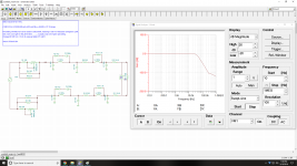
I have used this software for filter synthesis with passive components and gotten really good results:
Register for Filter Free You can create complex passive filters quite easily and it does a full modeling of them. Then copy into LTspice or whatever to tweak. I used it for a low pass reconstruction filter for a DAC and got a 90 dB measured reduction in image energy. Better than the recommended active filter.
The parts I used were off the shelf inductors form Coilcraft. Even though they have ferrite cores no measurable distortion from them.
Thanks Demian I'll check it out.
I've been using Tina from TI, but only because that's what I'm used to. Only dabbled a bit with sim software the past few months, not something i have much experience with.
I have used this software for filter synthesis with passive components and gotten really good results:
Register for Filter Free
I downloaded and installed only to find that the free version is severely constrained to design 3rd order or below. Not particularly useful.
If anyone wants to design higher order Chebyshev filters I have made plenty of designs using this resource (which goes up to 11th order) : Chebyshev Pi LC Low Pass Filter Calculator
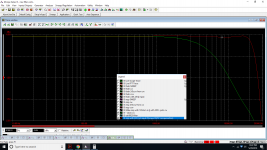
One more rev, 92R (not 91) in front to 33N.
Within .25db all the way to 20k and a bit more rolloff. Not quite as good as the original in flatness, but damn close.
Fyi there is an aux-0025 on ebay, a bit pricey imo though.
Fwiw, after playing with the original design more in depth in sim.. that's quite hard to beat in flatness once actually playing with adjustment possibility/cal.

Damn close was not a very accurate statement i made earlier
Anyway, i ordered a chassis (Redco CH1/6 6" Deep 1U Rackmount Chassis | Redco Audio)
Going to make the original filter on one side and my own sharper roll off on the other (once i'm satisfied with something). I wanted to just pick up an aux-0025 and modify one side, but no way i can justify the cost. Even for a used one.
I downloaded and installed only to find that the free version is severely constrained to design 3rd order or below. Not particularly useful.
If anyone wants to design higher order Chebyshev filters I have made plenty of designs using this resource (which goes up to 11th order) : Chebyshev Pi LC Low Pass Filter Calculator
I had not encountered the 3 pole limit. I think I may have had an older version.
The problem with the linked filter is that it's only for matched Z. The amp application needs something different. The source is essentially zero and the load is High Z. Anything else will have a load resistor getting hot and high current in the inductors.
I'll poke around for another free program. The NuHertz is quite nice but pricy.
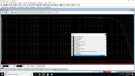
One more rev, parts should be here this weekend for build.
Got down to ~.075 db variance 0-20k under ideal cal vs about .03db on the original.
We'll see how it works in reality
Still planning on the original aux-0025 circuit on one half and this on the other.
Got down to ~.075 db variance 0-20k under ideal cal vs about .03db on the original.
We'll see how it works in reality
Still planning on the original aux-0025 circuit on one half and this on the other.
Attachments
Last edited:
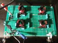
Grahhhh, had them space my xlr's out for me a bit and told them the typical xlr cutout size was fine.
The Neutrik through-hole mount xlr's i have are 2mm smaller in diameter.. another 40 bucks in parts from digikey coming, Switchcraft 23.5mm diameter xlr's will fit properly.
Still cheaper than an Ap filter.
Besides my oversight, redco box looks good. Seems prone to paint flaking off where xlr's were cut out but otherwise pretty good value on the box.
The Neutrik through-hole mount xlr's i have are 2mm smaller in diameter.. another 40 bucks in parts from digikey coming, Switchcraft 23.5mm diameter xlr's will fit properly.
Still cheaper than an Ap filter
.Besides my oversight, redco box looks good. Seems prone to paint flaking off where xlr's were cut out but otherwise pretty good value on the box.
Was seeing a couple db more rolloff with my new filter, took me awhile to realize what was going on. I've had the dscope on minimum output impedance (50R) for testing obviously but...
Lower inZ means design is more finicky with variances on DUT outZ.. duh. Can see the same on the Aux-0025 design but with higher inZ, it isn't as bad.
Will probably tweak the 2.49k parallel resistors a little lower to help center me up a bit more (while figuring on very low amplifier DUT output impedance - will be a little trial and error to get things happy).
Then move on to building the original too on the left side.
Attachments
Last edited:
Hi Ben
The AUX0025 was designed to work with the AP's. The short cables and the input Z of the AP's (100k Ohms & shunt C) is part of the filter. I spent many hours in the design of the filter to insure the working of the final product. The goal of the filter was to remove or reduce any carrier from causing distortion in the input stage of the AP's while keeping flat frequency response in the audio band.
Your version of the filter should work for you.
Duke
Hi Duke,
I was looking more at output impedance of the analyzer gen and how that affects how the filters perform when measuring it using only the analyzer.
The aux0025 doesn't care as much if the output impedance to it's input is higher (within reason, like 50ohms) since the resistance at inputs are higher.
Something I didn't consider when making my version..
End of day, amplifier's output impedance should be very low, so don't think I'm far off.. the design was simulated with 0ohms outZ from DUT though. Add 50ohms total, and I'm down 1.8-2.6db with this design at 20k.
Last edited:
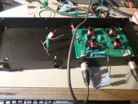
Lots of mains hum pickup with just the large aluminum case and no shielding. Didn't have the issue in my first smaller filter iirc, or maybe didn't notice it.. Probably some of both.
I have this sorted out for now by mounting the box up high and away from everything else. Cmrr is dialed in.
Any comments on shielding? Know non ferrus is important near inductors to keep good linearity.. wonder if the 0025 has aluminum shields inside and a steel outer case?
I have played with case grounding and currently have it connected to ground via a couple film 2u caps, one on each side. Seemed to give me the best results. The joints in case sections did not originally connect electrically, they have all now been sanded so it's one solid grounded piece.
Last edited:
Hi Ben
The AUX0025 has Steel outer shields for Electromagnetic fields and Alum inside for reducing the Electrostatic fields from the inductors. A complete Alum box will only keep the Electrostatic fields from entering the circuity. I though that i covered this on an old post. The AUX0025 can be on the top or bottom of the AP and no "HUM fields" will affect the measurments.
Duke
Hmm, well guess i screwed that up.. Was thinking I'd use an aluminum case so I wouldn't wreck inductor linearity.. but they aren't close enough to case for that to happen I suppose. Agreed aluminum does little to block mains hum from entering the circuitry.
Suppose if I want to fix it and be able to place the box somewhere more convienient, I'll need to get a new case or fit some steel sheets around it.
60hz and harmonics are barely showing out of the analyzer residual with it away from other equipment, so I guess I might just leave it where it is too....
- Status
- This old topic is closed. If you want to reopen this topic, contact a moderator using the "Report Post" button.
- Home
- Design & Build
- Equipment & Tools
- Passive Filter for Class D Amp Testing