I really appreciate your fast answer, especially since i'm just a guest on this forum. I'm mostly active on local Croatian diy forums and sadly don't have time to be active on this one so i mostly visit it now and then and read some interesting topics.
Here is picture of 4053 and how i understood it should be connected. Is this correct?
About designing PCB, i don't have much experience with inductive components, but i have designed quite a lot of PCBs for power supply,hi-fi amps,etc. And on our local forum we got few people that know electronics as back of their hand so i know i'll get good support from them.
Just a wild guess, but would be good to put each inductor into some casing? I know in VF devices they are in casings. That should prevent unwanted couplings,i think. And couple of pages before you mentioned that PCB design shoudn't be too compact so if we take all this in considerations i could brew some decent PCB.
And ofc when i finish PCB i would test it, no use to put public untested board and hope it turns ok.
That's it for now, after i make some progress with layout i'll put couple of pictures here until then cya.
Attachments
Hi Elvee,
I have a pair of 428B current meters that I still use. I would love to make a solid state version that uses the same probes. On thing I don't like about those meters is the size of the case. Worst case, I could simply install the solid state version inside the cases, maybe for an upgrade in stability and accuracy as they would probably hold calibration better - not that I can complain about the tube version.
I wouldn't be adverse to getting a smaller case and use the same meter and socket for the probe with everything else new. It would be really nice if I could stack them on top of each other, bench space being at a premium.
It's been a long time and I can't remember where you got to with this.
I very recently picked up an Agilent 34134A DC current probe for about $125 US. It isn't as sensitive as the 428B is, so for some applications the 428B is still the better bet. I think its more accurate too. It would be a nasty thing to find out how much Keysight would want for a current probe with the same or better sensitivity as the old 428B. Over $1,000 easily I bet.
-Chris
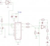
Yes, although the symbol is not drawn in a very coherent way, with in A controlling operator X, B for Y etc., but I think you have understood the principle.Here is picture of 4053 and how i understood it should be connected. Is this correct?
No, that's mostly unnecessary: clearances and orientation are your best friends. You can certainly find details on HAM sites.About designing PCB, i don't have much experience with inductive components, but i have designed quite a lot of PCBs for power supply,hi-fi amps,etc. And on our local forum we got few people that know electronics as back of their hand so i know i'll get good support from them.
Just a wild guess, but would be good to put each inductor into some casing? I know in VF devices they are in casings. That should prevent unwanted couplings,i think.
The only exception would be L5: you can see it on this pic (top right):
You will probably have to wind the transformer L2/3/4 and the coil L5 yourself.
For L5, I was lucky enough to find a ready-made one from an old TV horizontal oscillator, but that was unlikely.
Again, for information about winding, use HAM informations.
Yes, for me too, size was one of the main drivers behind this projectOn thing I don't like about those meters is the size of the case.
You are not alone....bench space being at a premium.
I use it constantlyIt's been a long time and I can't remember where you got to with this.
Hi Elvee,
I am extremely interested in your design, the lack of a PCB is the only thing holding me back right now. It's just a time thing, nothing else.
I still think it is an amazing project, and with the sensitivity it has (1 mA FS), very hard to beat. That's the sensitivity of the original unit.
Best regards, Chris
Got some more questions now when i saw picture you posted.
I see there are quite a few parts in sockets on right side, should i consider that while designing PCB or it's not needed. I know sockets are there cause you probably changed values of elements while adjusting device but is that really needed?
I forgot to ask earlier about 200uA range. I see there are three sections of S1 switch. My guess would be that on 200uA range S1C is connected/shorted and when you change to 2mA range S1C opens,is that correct?
About PCB design, i was thinking doing SMD(mostly 0805 size) with ground plane on one side. I got some experience with that. Ofc i wouldn't make it too small cause of reasons you already said. I'm not sure how people feel about soldering SMD on this forum but on mine we don't have much problem with that.
And i was thinking adding rotary switches directly to board or at least using some adapter board with rotary switch that would attach directly to main board, i'm not sure how would that be possible layout wise but as idea i think should be good.That would mean less wires that could cause and catch some interferences. Recently i designed that way board for analogue function generator and proved to be really good.
Hi Elvee,
I am extremely interested in your design, the lack of a PCB is the only thing holding me back right now. It's just a time thing, nothing else.
I still think it is an amazing project, and with the sensitivity it has (1 mA FS), very hard to beat. That's the sensitivity of the original unit.
Best regards, Chris
Just be patient, board should be on the way... i think after so many years since Elvee made schematic few months more or less is nothing.

For some, yes I think so otherwise you will have to use high precision L and C components (0.1 or 0.2%), which will be costly and inconvenient.Got some more questions now when i saw picture you posted.
I see there are quite a few parts in sockets on right side, should i consider that while designing PCB or it's not needed. I know sockets are there cause you probably changed values of elements while adjusting device but is that really needed?
A few are explicitly indicated (R106 for example), the rest are the padding capacitors across the inductors: C20, C21, in my case 1n8 as the main cap and 330p as padding, but you might need other padding values and C13 (main cap) + C14 (padding).
Reread carefully the whole thread and the alignment procedure, there are probably indications on how to select them.
You are rightI forgot to ask earlier about 200uA range. I see there are three sections of S1 switch. My guess would be that on 200uA range S1C is connected/shorted and when you change to 2mA range S1C opens,is that correct?
Yes, getting rid of wires is certainly beneficialAnd i was thinking adding rotary switches directly to board or at least using some adapter board with rotary switch that would attach directly to main board, i'm not sure how would that be possible layout wise but as idea i think should be good.That would mean less wires that could cause and catch some interferences. Recently i designed that way board for analogue function generator and proved to be really good.
Yes, it goes without saying that the usual rules about CMOS (including what to do with unused inputs/operators) have to be adhered to, but this is not a project for beginners, and those experienced enough to embark on it should have at least that kind of basic knowledgeHi Khadgar2007,
The INH pin on U5 should not be left floating but instead should be tied to logic low to make the function reliably active. Good practice would also tie the C pin to ground to ensure low current draw.
Good luck!
I think i covered everything so faar. Forgot to say that i added decoupling caps to all OPamp supply rails and other IC's can't do harm and should be usefull.
One last question before i start designing PCB.Is it ok if i post schematic on our local forum and do that there, would be a lot easier for me. I know you made it public here but i thought it's better to ask first.
One last question before i start designing PCB.Is it ok if i post schematic on our local forum and do that there, would be a lot easier for me. I know you made it public here but i thought it's better to ask first.
Thank you.
I will post link to this topic and when i finish PCB,will take some time, i'll attach entire project here.
edit: This is forum where i'll design PCB HP428B strujna sonda
Best regards,
Davor
I will post link to this topic and when i finish PCB,will take some time, i'll attach entire project here.
edit: This is forum where i'll design PCB HP428B strujna sonda
Best regards,
Davor
Last edited:
It's been a while since i posted anything in this topic or work at all on this project.I have been quite busy latety and didn't had time to work on this project. I have draw schematic in EAGLE and finally i'll be working on layout,but i have few questions.
I got quite a lot styroflex capacitors and question is use them or some modern quality caps,values is not issue, i already found quite a lot styroflex that match values on schematic. Other question is related to first, i would like to use SMD 0805 resistors,caps for power supply decoupling(100nF) and maybe some other caps that i cant find styroflex value. So question is would it be better to use quality smd caps in all places then combine styroflex with smd resistors.
I could add some small styroflex on some places but i think that using quite large styroflex caps(some are big as average 5W resistor) together with small 0805 resistors is not great idea. With smd design i would like to make all traces as short as possible but with adding big styroflex caps i think all positive things i would get with short traces would be nullified since traces to styroflex caps in most cases would be long and big caps have tendency to collect noise from surroundings.
I would think COG ceramic would be fine substitutes for the Polystyrene caps and are SMT. There are several shops in China that will make a short run of boards and load parts for very reasonable prices. If you go down that route I would be interested in one. I have an HP428 but its big and clumsy.
I was thinking same thing.On our local forum we have designed good signal generator for audio with low THD using COG caps in most places so i was thinking why not do same thing here. But i'm waiting what will Elvee say about this.
My design will have rotary switches solder directly to PCB,like on picture below.
This is picture of that signal generator.Other side of PCB is ground plane with some THT components.

I'll try to make PCB as much DIY friendly, so if you wanna make it at home it shouldn't be big problem.
My design will have rotary switches solder directly to PCB,like on picture below.
This is picture of that signal generator.Other side of PCB is ground plane with some THT components.
I'll try to make PCB as much DIY friendly, so if you wanna make it at home it shouldn't be big problem.
For tuning capacitors, group I ceramics are OK, SMD or TTH.So question is would it be better to use quality smd caps in all places then combine styroflex with smd resistors.
Styroflex has a moderate negative tempco, which can be advantageous since parasitic capacitances and inductors tend to have a positive tempco, but here the tuning is not that critical, meaning COG or NPO is perfectly adequate.
If you can find -75 or -150 types (or a combination resulting in a similar value), it would be even better, but it is by no means required
I have reread entire topic to refresh my memory and came to interesting puzzle.
S1 switch, needs to be 3P6T,i completely forgot about it. So i did some search and coudn't find PCB version of it so i guess some creative thinking is needed.
Plan is to look at any kind of rotary switch that is 3p6t or more(4p6t) and mount it like on PCB like on front panel with a screw then with short wires connect it to PCB.
For other switch ordinary lorlin 2p6t pcb mount should be fine.
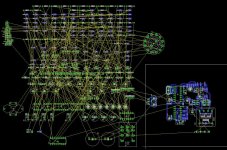
So far this is layout, a lot of work to be done. Atm i'm fiddling with transistors q1,2,5,6 and how to route traces around them. And ofc Q4,5,6 should be thermally connected.
Btw my M.O. when i'm making layout is that i place components,route traces and after i'm satisfied with that then i modify traces width,distance between components and traces etc.
S1 switch, needs to be 3P6T,i completely forgot about it. So i did some search and coudn't find PCB version of it so i guess some creative thinking is needed.
Plan is to look at any kind of rotary switch that is 3p6t or more(4p6t) and mount it like on PCB like on front panel with a screw then with short wires connect it to PCB.
For other switch ordinary lorlin 2p6t pcb mount should be fine.
So far this is layout, a lot of work to be done. Atm i'm fiddling with transistors q1,2,5,6 and how to route traces around them. And ofc Q4,5,6 should be thermally connected.
Btw my M.O. when i'm making layout is that i place components,route traces and after i'm satisfied with that then i modify traces width,distance between components and traces etc.
Attachments
Hi Khadgar2007,
I don't know about you, but I have not had any good luck long term with Lorlin switches. About the only good thing about them is that they are cheap. For a project like this that will be in use 40 years from now, maybe a better switch might be in order?
-Chris
I don't know about you, but I have not had any good luck long term with Lorlin switches. About the only good thing about them is that they are cheap. For a project like this that will be in use 40 years from now, maybe a better switch might be in order?
-Chris
C&K make interchangeable switches to the lorlin switches Series details | C&K switches But I would seriously look at relays or some other solution to a 2P6T switch today. Electroswitch has parts as well but wiith relays at $1 ea and switches getting pricey relays can make a lot of sense.
Here is the last version of the HP (made by some ex HP guys) Applied Physics Systems 428C Clip-on DC Milliammeter + HP Agilent Current Probe | eBay you can see their implementation with buttons and relays or ? fet switches.
Here is the last version of the HP (made by some ex HP guys) Applied Physics Systems 428C Clip-on DC Milliammeter + HP Agilent Current Probe | eBay you can see their implementation with buttons and relays or ? fet switches.
- Home
- Design & Build
- Equipment & Tools
- Modernized HP428 clone