After more than 10 years from the first design and a succesfull course in the DIY cycles, I am thinking to redesign the accelerometer amplifier for the ACH-01 sensor.
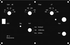
This new upgraded version of the device will have more Gain selections, Low Pass and High Pass filters with selectable frequencies and a LED clipping indicator circuit for monitoring the output signal.
Some of these functions were suggested from builders of the first design.
Here is a first version I made for the new front panel . Any other comment or suggestion are welcome.
Attachments

After more than 10 years from the first design, I just finished the redesign of the accelerometer amplifier for the ACH-01 sensor.
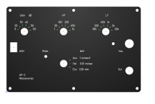
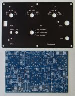
This new upgraded version of the device has more Gain selections, Low Pass and High Pass filters with selectable frequencies, a LED clipping indicator circuit for monitoring the output signal and a notch filter to supress the mains frequency which appears when the gain is above 50 dB.
Here attached is the front panel showing all the functionality of the device.
I 'm going to order some PCBs and Front panels.
Is there any interest from anyone to build this new version of the accelerometer amplifier ?
Attachments
Each ACH-01 accelerometer sensor is sold calibrated from the manufacturer in mV per acceleration units at a specific frequency.
Typical values are around 8 to 10 mV per g at 1 kHz.
Knowing the acceleration and frequency you can then calculate the velocity and from this the excursion using simple integrator circuits.
At the output of each integrator, a trimmer adjusts the proper value of voltage.
Typical values are around 8 to 10 mV per g at 1 kHz.
Knowing the acceleration and frequency you can then calculate the velocity and from this the excursion using simple integrator circuits.
At the output of each integrator, a trimmer adjusts the proper value of voltage.
I just finished the testing of the prototype of the new ACH accelerometer amplifier.
It is much more versatile if you want to investigate vibration issues due to the Low Pass and High Pass filters and the capability to use Gain amplification up to 60 dB.
Also the monitoring of the overload at the output helps to set correctly the Gain switch.
But the most interesting thing, for those who have used the ACH accelerometer and they know better the problem, is the notch filter to remove the mains interference (50 or 60 Hz).
It works very well, it offers an attenuation of about 30 dB and has a high Q of 10.
It is especially helpfull if you want to measure very low vibration signals with the Gain switch set at 30, 40, 50 or 60 dB.
Also a trimmer accessible from a hole in the front panel offers the capability to adjust more precisely the notch frequency, in case there is a need.
I already have a few PCBs and I'm going to order the Front panel to complete the design.
If someone is interested for the PCB and the Front panel of the new design, please send me a message.
A larger quantity for the front panel will help to have better prices and I will make a very special price for the set (PCB and Front panel) to those that are willing to help on this early stage.
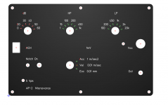
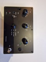
Here is the final Front Panel:
It is much more versatile if you want to investigate vibration issues due to the Low Pass and High Pass filters and the capability to use Gain amplification up to 60 dB.
Also the monitoring of the overload at the output helps to set correctly the Gain switch.
But the most interesting thing, for those who have used the ACH accelerometer and they know better the problem, is the notch filter to remove the mains interference (50 or 60 Hz).
It works very well, it offers an attenuation of about 30 dB and has a high Q of 10.
It is especially helpfull if you want to measure very low vibration signals with the Gain switch set at 30, 40, 50 or 60 dB.
Also a trimmer accessible from a hole in the front panel offers the capability to adjust more precisely the notch frequency, in case there is a need.
I already have a few PCBs and I'm going to order the Front panel to complete the design.
If someone is interested for the PCB and the Front panel of the new design, please send me a message.
A larger quantity for the front panel will help to have better prices and I will make a very special price for the set (PCB and Front panel) to those that are willing to help on this early stage.
Here is the final Front Panel:
Attachments
The cost depends on how many will be interested.
I estimate that the total cost for one PCB and one Front panel (without shipping cost) will be from 70 to 90 Euros.
The shipping cost will be around 10 Euros for Europe, something more for other countries.
For the BOM of the amplifier, my estimation is about 80 Euros. The cost could be reduced a lot if someone has built the previous version, because most of the components of the previous version can be used in the new version. Of course there are some other additional components due to the new features.
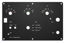
Here is a photo of the assembled AP-2 accelerometer amplifier.
I will wait for a few days to see if someoneone else is interested for the new PCB and Front panel and then I will proceed with the ordering of the Front panels.
Please, send me a message if you are interested.
I will wait for a few days to see if someoneone else is interested for the new PCB and Front panel and then I will proceed with the ordering of the Front panels.
Please, send me a message if you are interested.
Attachments
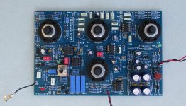

I've just completed my AP-2. The build was fairly straightforward.
The only alteration I've made is to add some mechanical support to the pcb header that the ach-01 plugs into. Without this I think the pcb tracks will flex and break.
I now have a sensitive and low noise vibration tester to assist in my upcoming speaker project. Thanks to George (gdan) for his assistance and for offering his design to the diy community. 
Attachments
- Home
- Design & Build
- Equipment & Tools
- Accelerometer Testing of Loudspeaker Drivers