The Murata PKGS-00GXP1-R is only a few bucks, weighs about nothing, and has bandwidth out to 20kHz. https://www.mouser.com/datasheet/2/281/KGS-00GXP1-R-792947.pdf
But that's only the good news.
The bad news is that it requires a buffer or a charge amplifier nearby, the output is low so amplification can be tricky (particularly at low frequency), and it needs to be in a fully shielded envelope. I made some based on the following schematic and got pretty good results.
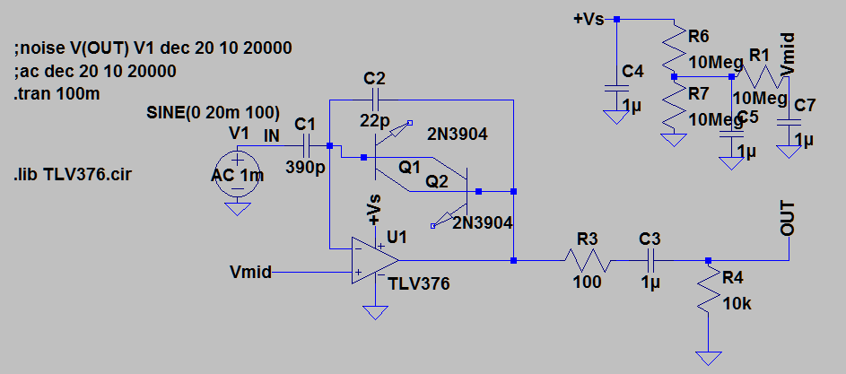 The sensor is represented by 'V1' and the 390pF cap -- don't put the cap in the circuit, just the sensor.
Vs is between 2.7V and 5V. The sensor is sensitive in the axis of the long edge, so either set the board on-end or mound the chip on edge. Again, the need for shielding is no joke. The two partially-connected transistors act as very-low-leakage diodes for bias and the impedances at the opamp inputs are very high so they pick up hum like crazy given a chance. You also need to keep the board clean (alcohol rub after soldering seems to do ok). The circuit can be made with very low mass, but the shielding can get heavy. The ACH-01 uses silver conductive paint (that can flake off if you use it for servo feedback in a subwoofer as I found out!). Perhaps this circuit can be made on a board, sealed in a small plastic jacket, and painted with silver print like that?
The ACH-01 has a heavy mass of metal (brass?) inside, which helps its sensitivity but adds mass to whatever is being tested. This guy is very light, but needs nearby, shielded amplification to get similar sensitivities.
But that's only the good news.
The bad news is that it requires a buffer or a charge amplifier nearby, the output is low so amplification can be tricky (particularly at low frequency), and it needs to be in a fully shielded envelope. I made some based on the following schematic and got pretty good results.
Vs is between 2.7V and 5V. The sensor is sensitive in the axis of the long edge, so either set the board on-end or mound the chip on edge. Again, the need for shielding is no joke. The two partially-connected transistors act as very-low-leakage diodes for bias and the impedances at the opamp inputs are very high so they pick up hum like crazy given a chance. You also need to keep the board clean (alcohol rub after soldering seems to do ok). The circuit can be made with very low mass, but the shielding can get heavy. The ACH-01 uses silver conductive paint (that can flake off if you use it for servo feedback in a subwoofer as I found out!). Perhaps this circuit can be made on a board, sealed in a small plastic jacket, and painted with silver print like that?
The ACH-01 has a heavy mass of metal (brass?) inside, which helps its sensitivity but adds mass to whatever is being tested. This guy is very light, but needs nearby, shielded amplification to get similar sensitivities.
Attachments

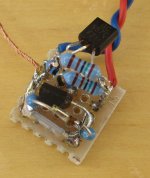
I have also done a lot of experiments using Murata PKGS-00LDP1-R (now obsolete) which is similar to PKGS-00GXP1-R. It is also very sensitive to hum and it needs shielding to be usable. In the photo, a small amplification circuit for the Murata sensor is shown with the shielding removed.
My system (based on ACH-01) that is described in the article is more suitable for vibration measurements of loudspeaker cabinets, turntables and similar things.
For these cases I think the ACH-01 is much more convenient and easy to use.
I also use the ACH for measurements on woofer's cone like the ones in previous posts but in this case it is not permanently attached to the cone.
Attachments
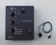
A reminder for anyone interested to build the accelerometer amplifier.
PCB and front panel are available.
More info here:
PCB and Front panel for Accelerometer preamplifier
PCB and front panel are available.
More info here:
PCB and Front panel for Accelerometer preamplifier
An interesting measurement I performed recently with the accelerometer system.
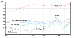
I placed the ACH accellerometer first on the middle of the loudspeaker cone and then in several places on the panels of a well braced loudspeaker box.
As shown in the attached figure the most noisy place was the Plastic mounting panel for the 4 gold-plated binding posts. Because it has to support 4 terminals it has a rather large plastic area.
What I learnt is that every detail matters if you want a very quiet cabinet.
Attachments
A technique I've used in the past is to generate an audio tone from a microcontroller using DDS, and simultaneosly an output pulse train at a frequency a few Hz higher. The pulses are routed through a current buffer to a large LED (3W star or bigger). The audio is fed to amp and speaker, LED pointing at speaker to illuminate it stroboscope style.
With around a few percent duty cycle on the pulses you get a nice stroboscopic view of the cone moving at a few Hz (while sweeping the actual frequencies).
With around a few percent duty cycle on the pulses you get a nice stroboscopic view of the cone moving at a few Hz (while sweeping the actual frequencies).
... the most noisy place was the Plastic mounting panel for the 4 gold-plated binding posts....
If you measure acceleration and want acoustic output, you must allow for the area of the radiating object. Assuming your panel is much smaller than your woofer, the acoustic output is another 10dB or 20dB down. Making 60dB or more difference of sound in the room. This could give a + or - 0.01dB peak or dip. Probably not audible.
If you measure acceleration and want acoustic output, you must allow for the area of the radiating object. Assuming your panel is much smaller than your woofer, the acoustic output is another 10dB or 20dB down. Making 60dB or more difference of sound in the room. This could give a + or - 0.01dB peak or dip. Probably not audible.
Actually the woofer has an active area of 72 cm2 (it is a 130mm driver) and the terminal panel has an area of 60 cm2. So they are close.
But even in this case, 50 dBs down is a very good result and should be no serious problem.
My point was that everything should be measured with the proper tools (like the ACH accelerometer and the amplifier), if someone is looking for a very quiet box.
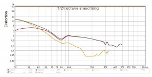
The ACH accelerometer with the amplifier can be used to measure the distortion of a loudspeaker at the Low Frequencies by attaching the accelerometer to the woofer's cone.
Here is a measurement of a 17cm woofer placed in a 12 liters Closed Box. Voltage is 4 Vrms.
Here is a measurement of a 17cm woofer placed in a 12 liters Closed Box. Voltage is 4 Vrms.
Attachments
gdan, can you elaborate on how the result plot was measured? Of interest is whether the plot was a smoothed set of single frequency measurement points based on a steady state condition at each frequency, or a sweep of excitation. Given the use of a constant excitation voltage, do you have a speaker impedance plot and could you infer a speaker cone x direction peak movement plot?
It is very easy, similar to a measurement of the frequency response.
Just replace the microphone and its preamplifier with the accelerometer and my amplifier.
The distortion was measured using the REW software.
The REW uses a log frequency sweep as an excitation signal.
The output of the sound card was connected to a power amplifier which drove the woofer with 4 Vrms.
The ACH accelerometer was attached to the woofer cone and connected to my accelerometer amplifier.
The output of the accelerometer amplifier was the input to the REW software (through the sound card).
The accelerometer has also a calibrated excursion output (1mV=0.01mm).
So it can measure the peak displacement of the cone in mm directly using an peak voltage meter or (better) an oscilloscope.
A typical measurement using ARTA is shown in post #33.
You need to be cautious about relating the accelerometer output to distortion. Since the output is acceleration it increases with frequency. The driver acoustic output is not quite that. Its a useful tool for finding specific problems but that distortion plot won't directly match the acoustic measurement. Not to mention that the voice coil motion is not an exact replica of the cone or the acoustic wave coming from the cone.
The sound pressure in the far field is proportional to the acceleration of the radiator‘s surface when its geometrical dimensions are small compared to the wavelength of the sound.
Since we are talking for a 17cm woofer and the distortion measurement concern the low frequencies, I think the above is true.
But yes, in the higher frequencies the acoustic power will not match directly the acceleration.
Since we are talking for a 17cm woofer and the distortion measurement concern the low frequencies, I think the above is true.
But yes, in the higher frequencies the acoustic power will not match directly the acceleration.
gdan, my concern would be that the REW sweep of the excitation signal may not allow a 'steady state' operating condition to develop at any particular set frequency, and hence any measurement outcome (distortion value) may not be representative. I would have thought that modal type resonances would take time to build up a displacement amplitude, and similarly decay the displacement response as measurement frequency is increased.
I understand your concern.
That is why I took the meassurement using the longest length sweep that the REW provides (1M).
Of course, a check can be made at specific frequencies of interest using the signal generator.
I think it will be interested to make a comparison between a sweep measurement and a spot frequency measurement.
I'll put this on my list.
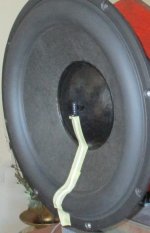
From time to time, I receive questions about the best way to attach the ACH-01 accelerometer on a loudspeaker cone.
This is what I do and I have always good results.
The ACH is attached using a small piece of double sided adhesive tape.
Its cable is attached firmly to the cone using masking tape (not very strong).
This is what I do and I have always good results.
The ACH is attached using a small piece of double sided adhesive tape.
Its cable is attached firmly to the cone using masking tape (not very strong).
Attachments
- Home
- Design & Build
- Equipment & Tools
- Accelerometer Testing of Loudspeaker Drivers