UPDATE 6/24/2018: I've updated some of the materials at the project Google Drive link. The BOM and front panel CAD files have been updated. Please see post #144 for the details.
UPDATE 4/22/2017: A new V3.2 board is available - please PM me. Very minor changes from V3.1, no functionality or part changes. if you already have a V3.1 you are not missing out on anything. I had run out of boards again and needed to send a new fab run in anyway. The change list is posted out on the Google Drive link and all the materials there have now been updated to V3.1 & V3.2. Boards will come with the only SMD part, IC2, pre-soldered on now (super tiny TSOT-23-5 thing) so the whole rest of the board is just easy to solder through hole. IC2 was also the only Digikey-only part, solving another problem. Also comes with the screws for mounting the board in a Hammond case and four M4 nylon spacers & nuts to use in the corner holes as feet for tabletop use. I did a much larger run this time so the board is $4 less even with the chip soldered on now.
UPDATE 8/6/2015: Victor has posted that his latest run of oscillator boards use a thinner 1.2mm board than the previous 1.5mm. The ground screw hole needs to be 0.3mm higher now if you are using a new board. I'm going to leave all the posted Front Panel Designer (free download at Front Panel Express) CAD files as-is, sized for the 1.5mm board, since it is easy enough to fire up the CAD program and raise the screw hole(s) 0.3mm. Some folks may wind up with a mix of old and new boards on a front panel if they already have an old board and then buy a new one from Victor for a different frequency.
All of the project materials posted in this thread are now also out on Google Drive here:
Victor's oscillator front panel and power supply - Google Drive
**************
Original post:
I recently bought Victor's 1kHz and 10kHz oscillators after skimming through the long thread here that I haven't been following until now.") I've spent a couple of hours with the thread so far but haven't seen anyone publish a case and power supply to use with his oscillators, so here goes since I need one myself. I'll post the Gerbers and FPE panel CAD file when the board is back and I've verified it works. If anyone has ideas or suggestions on ways to improve, or spots anything that I'm screwing up, please post!
I've spent a couple of hours with the thread so far but haven't seen anyone publish a case and power supply to use with his oscillators, so here goes since I need one myself. I'll post the Gerbers and FPE panel CAD file when the board is back and I've verified it works. If anyone has ideas or suggestions on ways to improve, or spots anything that I'm screwing up, please post!
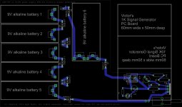
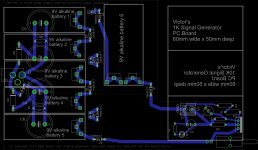
The case is the extruded aluminum Hammond 1455N1601 (or 1455N1601BK for black or BU for blue) which is $24 at Mouser and Digikey right now with a bunch in stock. The case is designed for a 100mm wide by 160mm long PC board. I'm using a 2 layer here and so far I've been able to keep everything to the bottom layer. It would probably be possible to home-etch it, although I'm going to send it out for fab.
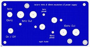
The case should be tall enough to fit both of Victor's boards together, as the front panel image below shows. His 10kHz board is on the bottom and his 1kHz board is upside down on the top. At 27mm tall each the board won't fit the 49mm tall case if stacked with both right side up, which is why the upside-down interleaving. The 1kHz is shifted to the left so the tall electolytics in the back of Victor's boards miss each other. The 160mm x 100mm power supply PC board is notched out around Victor's 10kHz oscillator board on the bottom. I tried fitting it all into a Box Enclosures B3-160 extruded case, also 100 x 160mm, but at 8mm less tall it doesn't appear the oscillator boards would clear in any configuration.
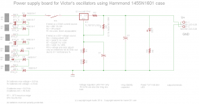
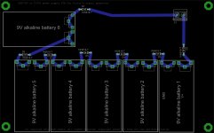
The power supply board sits in back and the left side and consists of 6 9V alkaline cells. The 5 in back sit on edge and wedge in between the back panel and a 9V PCB snap on the PC board. Pairs of cells have their top terminals bridged by 9V snap pairs with wire leads. The 6th cell is wedged between the case sidewall and the two PCB battery snaps. I have Schottky (for low Vdrop of course) diodes between all the cells to take into account someone accidentally touching the battery terminal with the battery backwards - lol I do it all the time. I know I'm going to have to find something with a higher PIV than the 40V of those 1N5819's. Any suggestions are welcome...
I'm using 6 cells since the 9V alkaline discharge curve here (scroll down) goes from 9V to around 6.5Vdc before dropping off a cliff. That gives 6.5Vdc x 6 = 39Vdc minimum, still above the 35Vdc target and a nice 4V across the Vreg. On the high side that would be 9Vdc x 6 = 54Vdc, which is well within the maximum 60V input spec for the LM317HV regulator or 125Vdc for the TL783 regulator. Turns out the LM317HV and TL783 have the same pinout and are the same mechanically, with the exception of the LM317HV tab being a tiny bit thicker.
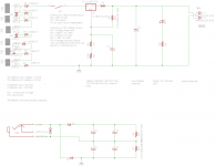
The regulator is in the TO-220 package and bolted to the front panel for heat sinking. I've kept all the holes on the front panel so only one uber-expensive Front Panel Express panel is needed (their ordering program totals up $37.92 USD plus $5 shipping for the design). I've set the board up where it can either be wired as a 35Vdc voltage regulator or a 25 mA current source in the typical fashion. The notes on the schematic give the details. In the case of the current source the 100 R resistors on the power lines on Victor's board are jumpered, as suggested in the thread.
I'm using batteries to preserve the ultra low noise floor that Victor's oscillators apparently have from all the AP measurements in the thread. I originally was considering a voltage doubler AC supply with a 24 Vac transformer input. I think it would be difficult to keep the power line harmonics out of the oscillator, at those super low noise floor levels, if the AC supply were in the same box and without a metal shield around it. The current draw is low so the batteries should last a fairly long time. The four front panel mounting screws would have to come off and the whole assembly slid out to change the batteries.
There is one off-board panel mounted switch to send the power either to the 1 kHz oscillator or the 10 kHz. The power supply could easily power both at once. My thinking though is the two signals would get into each other and mix given the close proximity of the two oscillator boards here, especially facing each other like this with one upside down. Probably best to only have one oscillator board powered up at a time.
On the front panel I've specified a small 0.25 mm deep countersink around Victor's ground screws and one panel mounting screw to cut through the anodization for a good electrical contact. I probably should do the same around the pot shafts to use the pot nut and properly ground the shaft. The panel design is down with the free-download "front panel designer" on Front Panel Express (or Schaeffer AG in the EU, their parent company it seems) website. Using FPD the text or anything else on the panel can be easily modified.
UPDATE 4/22/2017: A new V3.2 board is available - please PM me. Very minor changes from V3.1, no functionality or part changes. if you already have a V3.1 you are not missing out on anything. I had run out of boards again and needed to send a new fab run in anyway. The change list is posted out on the Google Drive link and all the materials there have now been updated to V3.1 & V3.2. Boards will come with the only SMD part, IC2, pre-soldered on now (super tiny TSOT-23-5 thing) so the whole rest of the board is just easy to solder through hole. IC2 was also the only Digikey-only part, solving another problem. Also comes with the screws for mounting the board in a Hammond case and four M4 nylon spacers & nuts to use in the corner holes as feet for tabletop use. I did a much larger run this time so the board is $4 less even with the chip soldered on now.
UPDATE 8/6/2015: Victor has posted that his latest run of oscillator boards use a thinner 1.2mm board than the previous 1.5mm. The ground screw hole needs to be 0.3mm higher now if you are using a new board. I'm going to leave all the posted Front Panel Designer (free download at Front Panel Express) CAD files as-is, sized for the 1.5mm board, since it is easy enough to fire up the CAD program and raise the screw hole(s) 0.3mm. Some folks may wind up with a mix of old and new boards on a front panel if they already have an old board and then buy a new one from Victor for a different frequency.
All of the project materials posted in this thread are now also out on Google Drive here:
Victor's oscillator front panel and power supply - Google Drive
**************
Original post:
I recently bought Victor's 1kHz and 10kHz oscillators after skimming through the long thread here that I haven't been following until now.
I've spent a couple of hours with the thread so far but haven't seen anyone publish a case and power supply to use with his oscillators, so here goes since I need one myself. I'll post the Gerbers and FPE panel CAD file when the board is back and I've verified it works. If anyone has ideas or suggestions on ways to improve, or spots anything that I'm screwing up, please post!The case is the extruded aluminum Hammond 1455N1601 (or 1455N1601BK for black or BU for blue) which is $24 at Mouser and Digikey right now with a bunch in stock. The case is designed for a 100mm wide by 160mm long PC board. I'm using a 2 layer here and so far I've been able to keep everything to the bottom layer. It would probably be possible to home-etch it, although I'm going to send it out for fab.
The case should be tall enough to fit both of Victor's boards together, as the front panel image below shows. His 10kHz board is on the bottom and his 1kHz board is upside down on the top. At 27mm tall each the board won't fit the 49mm tall case if stacked with both right side up, which is why the upside-down interleaving. The 1kHz is shifted to the left so the tall electolytics in the back of Victor's boards miss each other. The 160mm x 100mm power supply PC board is notched out around Victor's 10kHz oscillator board on the bottom. I tried fitting it all into a Box Enclosures B3-160 extruded case, also 100 x 160mm, but at 8mm less tall it doesn't appear the oscillator boards would clear in any configuration.
The power supply board sits in back and the left side and consists of 6 9V alkaline cells. The 5 in back sit on edge and wedge in between the back panel and a 9V PCB snap on the PC board. Pairs of cells have their top terminals bridged by 9V snap pairs with wire leads. The 6th cell is wedged between the case sidewall and the two PCB battery snaps. I have Schottky (for low Vdrop of course) diodes between all the cells to take into account someone accidentally touching the battery terminal with the battery backwards - lol I do it all the time.
I know I'm going to have to find something with a higher PIV than the 40V of those 1N5819's. Any suggestions are welcome...I'm using 6 cells since the 9V alkaline discharge curve here (scroll down) goes from 9V to around 6.5Vdc before dropping off a cliff. That gives 6.5Vdc x 6 = 39Vdc minimum, still above the 35Vdc target and a nice 4V across the Vreg. On the high side that would be 9Vdc x 6 = 54Vdc, which is well within the maximum 60V input spec for the LM317HV regulator or 125Vdc for the TL783 regulator. Turns out the LM317HV and TL783 have the same pinout and are the same mechanically, with the exception of the LM317HV tab being a tiny bit thicker.
The regulator is in the TO-220 package and bolted to the front panel for heat sinking. I've kept all the holes on the front panel so only one uber-expensive Front Panel Express panel is needed (their ordering program totals up $37.92 USD plus $5 shipping for the design). I've set the board up where it can either be wired as a 35Vdc voltage regulator or a 25 mA current source in the typical fashion. The notes on the schematic give the details. In the case of the current source the 100 R resistors on the power lines on Victor's board are jumpered, as suggested in the thread.
I'm using batteries to preserve the ultra low noise floor that Victor's oscillators apparently have from all the AP measurements in the thread. I originally was considering a voltage doubler AC supply with a 24 Vac transformer input. I think it would be difficult to keep the power line harmonics out of the oscillator, at those super low noise floor levels, if the AC supply were in the same box and without a metal shield around it. The current draw is low so the batteries should last a fairly long time. The four front panel mounting screws would have to come off and the whole assembly slid out to change the batteries.
There is one off-board panel mounted switch to send the power either to the 1 kHz oscillator or the 10 kHz. The power supply could easily power both at once. My thinking though is the two signals would get into each other and mix given the close proximity of the two oscillator boards here, especially facing each other like this with one upside down. Probably best to only have one oscillator board powered up at a time.
On the front panel I've specified a small 0.25 mm deep countersink around Victor's ground screws and one panel mounting screw to cut through the anodization for a good electrical contact. I probably should do the same around the pot shafts to use the pot nut and properly ground the shaft. The panel design is down with the free-download "front panel designer" on Front Panel Express (or Schaeffer AG in the EU, their parent company it seems) website. Using FPD the text or anything else on the panel can be easily modified.
Attachments
Last edited:
Is that Ag Doctor? Or Silver Doctor?
That looks rather nice. I think that it is kind of needed.
Paraphrasing here Demian (1Audio) can tell you better and me. Demian has a model of Victors 1kHz oscillator using the the LM317 and 4 batteries I think. He mentioned that it doen't really need 35 volts to function correctly.
I'm not sure what he did...something about soldering the 317 directly to the 100 ohm SMDs or you put a resistor across it. And if you don't switch it off it will still last 30 - 40 hours.
I was going to try and do that with it and put is in a tea tin.
But, if you are having the boards made and the panel made punched etc, I would be interested.
Cheers,
Is that Ag Doctor?
Or Silver Doctor?
Lol!
"agdr" turned out to be my version of "asdf". When I started posting on the audio forums a few years ago I wanted a name completely different than what I use for a couple of other hobbies. Couldn't think of a thing though. So I just pecked out some random letters and came up with agdr. Then later on I learned the most commonly typed random letters are "asdf" so I wound up with two of the four at least. I did see 1audio's post and that is exactly why the board can be wired up as a current source too. He had a very good idea there. Those TL431's on Victor's board work by shunting whatever additional current they need to (past what current the main circuit is consuming) to maintain 2.5Vdc at their reference pin, which in turn is set up as a voltage divider from the power rail. Things are usually designed so that at the main circuit's minimum load the TL431 is shunting maximum current, as long as that amount is within the 100mA max sink rating for the chip. Then when the main circuit is using maximum current the TL431 reduces its current flow to keep the reference at 2.5Vdc, and hence the rail voltage steady at 15Vdc by way of the ref pin voltage divider.
So long story short, the TL431 and the circuit can be fed from some fixed current source like this. The TL431's will sink whatever amount of that current the main circuit isn't using to maintain the 15Vdc rail voltages. The current source has a very high impedance looking back into it of course, better than the 100R TL431 cathode resistors. If the input voltage to Victor's board is 35Vdc and the two rails are 15Vdc, then the existing design current is (35Vdc - (2 * 15Vdc)) / (2 * 100R) = 25mA. Those two 100R TL431 cathode resistors on Victor's board (his R32 and R33) would be just shorted across under the board since they are not needed with the current source feed.
Or... leave the 100R resistors and wire the board up as the 35V voltage source and that works too.
Hey good to know there is some interest in the board/case! I'm going to make it for myself regardless, so might as well share. For the first run of boards I'll probably only do the minimum of 5 (Seeed Studio's fusion service) since there is inevitably some screw-up in the layout. But if there is interest I may get a list together after that and do a larger run, sold at-cost of course. From their webpage:
Fusion PCB, customize PCB prototype | Seeedstudio
20 boards 100 x 160 (have to use their 100 x 200 service) with HASL finish would be around $98 plus probably $12 or so shipping, or around $5.60 a board. I would probably go with ENIG finish though (gold) which adds a dollar or so per board.
I am interested also... need the punched panel very much.
But want the pcb also.
Would like a set that holds three osc, also.
-RMarsh
Good deal! I'm going to run a test panel first before posting the panel FPE CAD file to make sure it all works as planned.
Front Panel Express' price comes down a tiny bit in quantity too. Their free FPD computer program has the discount built in. At 5 boards it gives 5% and 10 boards is 10%. FPE also runs the occasional discount promo on their Facebook page. They had 20% off for a while last summer. They are pricey but do excellent work. You can also mail them the panel that comes with the case and they will use that for the stock. I've done that a few times with Box Enclosure cases. That gives nice anodized edges which otherwise wind up as bare aluminum when they mill it out of a bigger sheet of their own material.
Just curious, why three oscillator boards?
I'll bet you are tuning one of them for something other than the stock 1kHz or 10kHz.Below is another idea for the board. Same board but pads for a voltage doubler circuit are added under the batteries. 24Vac in gives around 67Vdc into the regulator, which would have to be the TL783 chip in that case. The LM317HV and TL783 have the same pinout and mechanical package so either will work in the board, but the TL783 has 125Vdc max input.
That way the same board could be built up with an AC supply if someone wanted, although I still think the power harmonics would probably get into the oscillator. I'm thinking might as well include that circuit since the fab costs the same either way and it wouldn't interfere with the batteries if not used. I'm also thinking of going to two panel mounted power switches, one for each board (1 kHz and 10 kHz), rather than the one switch to select one board or the other. That way if someone really did want to run them both at the same time they could.
That is a bidirectional transorb across the transformer input in the voltage doubler. Then capacitor pads for 7.5mm lead spacing at 16mm or 18mm diameter, which as low-Z/low-ESR can be a 2200uF 50V or 1000uF 100V these days at Mouser it appears. The resistors are just high-ohm safety bleeders across the caps.
Attachments
Last edited:
agdr,
Thanks for the explanation. Please count me in for the boards and the front panel too. Trying to drill out tea tins is kinda messy.
I like the functionality of the dual supply board because if anyone else has my good luck I'd just get it all set up dialed in then the batteries would die. I'd go to replace them and be out or not have enough. If needed it's always nice to plug in.
Initially I was thinking it might be nice to have an ON - OFF - ON, for either but if ever their was a need to run both at once....
I'm wondering about front panel layout as one Oscillator is upside down guessing this minimizes power supply wire lengths. Limited middle space or end up three horizontal boards 2 Victors plus yours.
Not sure how it would affect things if oscillator boards were they were lined up vertically... | | Would simplify recognition of the man-machine interface and components. With small multiples or like multiples of the same.
It also might simplify scaling, that is: 1 victor's, 2 victor's, 3 victors'...more.
Maybe only slightly wider chassis.
Food for thought any way.
agdr,
That's not bad, someone could have come up with QWERTY. What if Jay Kay Ell Sem? LOL
I'm not trying to knock heads or anything just trying my hand at something that is easily recognizable and we don't need to think to use it.
Using small multiples or like multiples everything just kind of instinctively takes hold. Like analog clocks, gauges, meters, read outs, etc.... You look once and get a feel for it.
We don't need to process .25 or .75. Just by glancing at the clocks hands we know.
Of all the tasks that we do, writing, designing, coding, manufacturing, layout, testing, training, presenting...
...the most difficult task
...is keeping it simple.
Richard, you thinking something along these lines?
I slammed this together:
Last edited:
SyncTronX - good thoughts on the vertical mounting but the interior height of that Hammond 1455N1601 case is 49.6mm while Victor's board length is 59.75mm. So far that 1455N1601 case is the tallest extruded 100mm x 160mm with card slots that I've been able to find. If anyone knows of a taller case out there somewhere, please post!
The vertical height of Victor's boards would also prevent them both from being right-side up. They are 27mm tall, so make that 28mm with 1mm spacing between. 2 would be 56mm, more than that 49.6mm case height. By flipping one board over though it allows one board to encroach on the space of the other. The pot on one board sits a little bit above the RCA jacks on the other, and vice versa. Since the RCA jacks are short it all fits. Then moving one board to the left keeps those caps in the backs of his board from hitting each other.
Since there don't seem to be any taller 100mm x 160mm cases the best solution for 3 (or 4) boards is probably just to build a second case/power supply. I'll also post a front panel CAD with holes for just one of Victor's boards on the bottom, if anyone only wants to use just 1 of Victor's board (or a 3rd board in a second case).
I forgot to answer the question about the 6 batteries vs. 4. I'm designing it all for worst case, when the batteries run down after a long time and hit 6.5V each. 4 batteries would work as long as they are are fresh with voltage near the 9V or 8.5V end of things. From that discharge curve it doesn't look like "9V" batteries stay at 9V for long. They pretty quickly drop to 8.5V and then stay relatively steady in voltage drop over time from 8.5v down to 6.5V.
I would like to get some sort of "dead battery" indicator included to notify when the cells hit 6.5 x 6 = 39V. I've thought of a green LED in series with a 37V zener which would go off when the voltage was low, but I'm concerned about injecting any zener noise into the supply. If anyone has an idea on a low voltage indicator please post!
Last edited:
Hi agdr,
I found some boxes at digikey that might work. I selected 60.mm then got the other dimensions from their drop down list.
http://www.digikey.com/product-search/en?pv329=771&FV=fff40021%2Cfff803a6&mnonly=0&newproducts=0&ColumnSort=0&page=1&quantity=0&ptm=0&fid=0&pageSize=25
I think they might have some other boxes too, a variety of debths etc.
I see that you want it to lay flat front facing instead of facing up. Some of the old Hard Drive boxes might work that lay flat and have a tall enough face.
Also appreciate the PS explanation. I don't know enough about it all. If you don't mind what are the benefits or advantages and disadvantages of having a a voltage power supply vice current power supply?
If you don't mind also, I'm struggling over at the HP339a Distortion Analyzer thread, trying to figure out how to minimize 60 hz source 3rd harmonic modulation around the 1kHz notch filter. Last page is where I'm currently. I've also used Victor's oscillator as an input to the analyzer.
Cheers.
the power supply as suggested is not the most efficient way to do it. shunt current losses.
what Demian suggested is a CCS, a 317 with a resistor from the adj to the output and set for 16ma if I remember correctly. That is what I built up and it works nicely with (4) 9V batteries.
Using a CCS is useful here as the supply on Viktor's board is a shunt regulator and metering in the needed current is efficient.
Alan Garren
what Demian suggested is a CCS, a 317 with a resistor from the adj to the output and set for 16ma if I remember correctly. That is what I built up and it works nicely with (4) 9V batteries.
Yep, that is why the board can be configured either as a CCS or a voltage regulator. I just noticed on the schematic that I did a part re-number after I wrote those instructions on the schematic on how to do one or the other.
I'll fix that and re-post so the part numbers match the instructions. But to get a CCS with the LM317HV you populate R3 (the current set resistor), jumper the R4 position to tie the adjust to the output just like you say, then leave R1, R2, and C1 unpopulated.To make the board a voltage regulator instead with the LM317HV, jumper R3, populate R1, R2, and R4 (the voltage set resistors) and C1.
All of the above would also apply if using the TL783 instead of the LM317HV. Either will fit and work in the board.
To use 4 batteries instead of the 6, any two of the battery terminal positions can be jumpered. But once the batteries run down, at the 6.5Vdc end of things from that discharge curve link in the first thread post, that would only be 4 x 6.5Vdc = 26Vdc. Using 6 cells insures a minimum of 39V even a long time down the road when the batteries are low.
SyncTronX - so there is a excellent answer in waltzingbear's post to your question about why use a CCS.
Thanks for the pointer to the boxes, but I don't think those have the card slots for the 100mm x 160mm cards inside though. I can take a look at adding mounting holes on the corners of the board so it could simply be standoff-mounted in a much larger case as an alternative way to use it. That way any number of Victor's boards could be used. I'm still going to plug away at the 1455N1601 case design though since it results in a very compact and portable build. That is unless someone finds an extruded case with card slots for a 100x160 that is taller.
I unfortunately haven't been following that HP339A thread so I'm not going to be any help there. I'm using Victor's boards with my QA400.
Richard - that is what I was guessing you were doing, shooting for a lower frequency point. I would really like to do that too. 100Hz or 400Hz would be nice. But on my "quick" 2+ hour scan of the thread so far I think I saw at least one post (it may have been from Victor in fact) pointing out a technical problem with using lower frequencies. That probably was solved later in the thread. My reading there continues as time permits...
Last edited:
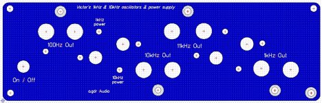
Well, if I was commissioning this for myself -- I would mount 4 pcb from Victor in it: 100hz (or less), 1KHz, 10KHz and 11KHz.
Those sound like an excellent set of tones. So good in fact I think that I would like to do the same eventually, probably with two case/power supplies. Maybe the 10kHz/11Khz in one and the 100Hz and 1kHz in the other.
4 of Victor's boards at once (or just 2) in a 160mm x 160mm extruded case
Another idea.
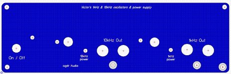
This change uses the larger 160x160mm Hammond 1455T1601 (1455T1601BK for black or BU for blue, all are in stock at Mouser) extruded case rather than the previous 100mm wide by 160mm long 1455N1601 case. Oddly enough the larger case is the same price, still around $24 depending on color at Mouser or Digikey. The mysteries of retail. The "T" case is just a tiny bit less tall, 2.03" vs. 2.09", but from what I can tell the boards will still fit if the top two are inverted. If only 2 of Victor's boards are being used then only the bottom two mounting positions are used (both right side up). A panel would be used that has just the holes for the bottom 2 boards, as below.
A side benefit of the larger case is that with only two boards they are now side-by-side (rather than one inverted over the other) and would be much less likely to interfere with each other. 2 boards should be able to work at the same time with very little interference from each other. With all 4 boards two are still inverted over the other two, but the way I have the panel laid out the 11kHz is over the 10kHz. In actual DUT usage those two would probably be running at the same time anyway.
Some other good stuff happens with the change. The "battery board" in the rear is now 160mm wide and 100mm long. The rear five 9V cells can now all lie flat and be secured with 2 PCB 9V snaps, rather than on end previously with the top two terminals bridged with leaded snaps. There is room now for 4mm holes in the corners, allowing the board to be mounted in a much larger case just using standoffs, rather than the card-edge slot extruded 1455T1601 case.
I'm still pondering what to do about the voltage regulator chip and parts. I could make the board a 160x160 to extend the voltage regulator to the front panel again. That would require the 20cm x 20cm fab process and result in a board around $12. It may be possible to fabricate just a small 40mm x 60mm PC board (which would be around $1.60) and have it supported by the switch and voltage regulator, leaving the back battery board at (the cheaper) 160x100mm size.
With the larger case and the batteries lying flat there would be around 20mm or so of free space above the batteries which might be useful for something. Victor's boards wouldn't fit there though since they are 27mm tall.
Another idea.
This change uses the larger 160x160mm Hammond 1455T1601 (1455T1601BK for black or BU for blue, all are in stock at Mouser) extruded case rather than the previous 100mm wide by 160mm long 1455N1601 case. Oddly enough the larger case is the same price, still around $24 depending on color at Mouser or Digikey. The mysteries of retail. The "T" case is just a tiny bit less tall, 2.03" vs. 2.09", but from what I can tell the boards will still fit if the top two are inverted. If only 2 of Victor's boards are being used then only the bottom two mounting positions are used (both right side up). A panel would be used that has just the holes for the bottom 2 boards, as below.
A side benefit of the larger case is that with only two boards they are now side-by-side (rather than one inverted over the other) and would be much less likely to interfere with each other. 2 boards should be able to work at the same time with very little interference from each other. With all 4 boards two are still inverted over the other two, but the way I have the panel laid out the 11kHz is over the 10kHz. In actual DUT usage those two would probably be running at the same time anyway.
Some other good stuff happens with the change. The "battery board" in the rear is now 160mm wide and 100mm long. The rear five 9V cells can now all lie flat and be secured with 2 PCB 9V snaps, rather than on end previously with the top two terminals bridged with leaded snaps. There is room now for 4mm holes in the corners, allowing the board to be mounted in a much larger case just using standoffs, rather than the card-edge slot extruded 1455T1601 case.
I'm still pondering what to do about the voltage regulator chip and parts. I could make the board a 160x160 to extend the voltage regulator to the front panel again. That would require the 20cm x 20cm fab process and result in a board around $12. It may be possible to fabricate just a small 40mm x 60mm PC board (which would be around $1.60) and have it supported by the switch and voltage regulator, leaving the back battery board at (the cheaper) 160x100mm size.
With the larger case and the batteries lying flat there would be around 20mm or so of free space above the batteries which might be useful for something. Victor's boards wouldn't fit there though since they are 27mm tall.
Attachments
Last edited:
Turns out the panel cost at Front Panel Express is about the same too, even though the panel is 60mm wider and has twice the amount of holes and lettering. $40 for the 160mm panel vs. $38 for the 100mm. Seems that most of their charge is the one-time tooling setup. A whole bunch of holes costs just a little more than one hole, and same with the engraved letters.
I have Schottky (for low Vdrop of course) diodes between all the cells to take into account someone accidentally touching the battery terminal with the battery backwards - lol I do it all the time.
It will not helps
Suppose you put 5 bats normally and one opposite - you will have 5*9-9=36V instead of 6*9=54V and the diodes will be forward biased.
Also there is no sence to put 6 diodes in series.
The current draw is low so the batteries should last a fairly long time.
A new alkaline 6LR 9V battery has a capacity 560 mA*h, one viktor's generator eat ~20mA, so it should me more the 28 hours.
(Lithium have the twice capacity!).
It is not very long time, trust me
Using non expencive NiMH rechargable batteries even worst - their capacity is 200-300 mA*h, or just 100 mA*h if to buy at cnineese E-Bay.
Also trust me
. Thats why I power it from the laboratory power supply (Tek PS280). By the way - the difference with the bttery supply is negligible.
Last edited:
- Status
- This old topic is closed. If you want to reopen this topic, contact a moderator using the "Report Post" button.
- Home
- Design & Build
- Equipment & Tools
- A case and power supply for Victor's low THD oscillators