Here is my latest project: I had felt the need for a different capacitance-meter, mostly aimed at big E-lytics or other high energy-storage technologies.
Normally, the measured parameters of capacitors in a good condition are not dependent on the current level. However, when a capacitor is in a marginal health condition, measuring it at 10's of µA or 10's of A can make quite a difference.
And of course, that is precisely for capacitors in a marginal state that such a knowledge is interesting
I therefore came up with schemes to measure capacitors at a (near) real-life level, in a meaningful way. Two of them have emerged, I chose the one I thought was the most versatile and promising (but I will probably build the other one as well).
It measures from 2µF to 2F full scale in 8 calibers, divided into 4 ranges and 2 sub-ranges, (that is a usable measurement range of 100nF to 2F), and on its highest scale, it can pass in excess of 50A through the cap under test.
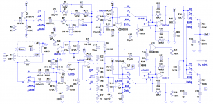
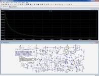
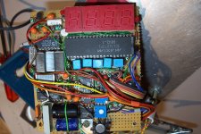
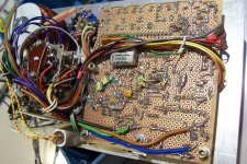
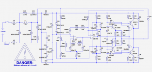
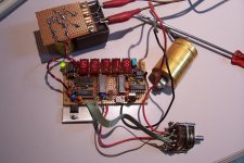
Here is already the schematic of the most important part, the acquisition engine, and a few pics of my prototype.
To be continued...
Normally, the measured parameters of capacitors in a good condition are not dependent on the current level. However, when a capacitor is in a marginal health condition, measuring it at 10's of µA or 10's of A can make quite a difference.
And of course, that is precisely for capacitors in a marginal state that such a knowledge is interesting
I therefore came up with schemes to measure capacitors at a (near) real-life level, in a meaningful way. Two of them have emerged, I chose the one I thought was the most versatile and promising (but I will probably build the other one as well).
It measures from 2µF to 2F full scale in 8 calibers, divided into 4 ranges and 2 sub-ranges, (that is a usable measurement range of 100nF to 2F), and on its highest scale, it can pass in excess of 50A through the cap under test.
Here is already the schematic of the most important part, the acquisition engine, and a few pics of my prototype.
To be continued...
Attachments

Last edited:
Before going further, I should make clear that this project is not really intended as something to be reproduced literally in every detail (although you are free to do so), but rather as a source of inspiration for personal implementations, for two main reasons:
-One is fundamental/theoretical: the type of capacitances it measures (theoretical, energy and bypass) have no official existence, they are my own pet definitions, and I am probably the only person finding them of interest.
-The other is more practical: I have built this meter using my stock of parts, and this includes a 5 position, 5 deck, 10 circuits selector, something that is probably not easy to source nowadays.
However, the principles and circuits are sound and robust, and they can be reused in many other personal interpretations/implementations.
Back to the acquisition circuit:
It is essentially a vector computer: the two channels, voltage and current across/through the capacitor are amplified and/or quadrature shifted, scaled, have a synchronization signal extracted and are vectorially demodulated in synchronous detectors.
The resulting signals are then ready to be arithmetically processed by the A to D converter.
The circuit is capable of computing basically any quantity: if you combine the 4 possibilities of Quadrature/In phase inputs, the 4 possibilities of sync signal to demodulate them, the 4 ways to apply them to the ADC (I to in or to ref, V to in or to ref, constant on either of the inputs), you end up with 64 displayable quantities, to which you can still add some direct phase options.
Not all of these quantities have an interest or even a physical meaning, but you still have a good choice of what to extract.
I have selected five of them, but as I said, it is a matter of personal taste (and the number of ways of the selector!).
The source of stimulus is a 0.4V AC direct from the mains transformer: I have used a 20VA toroid that I have partially rewound. The stimulus winding has 4 turns of 6mm² wire, and has a resistance <1.5mΩ.
When I designed the thing, I made a bet: that the heavily distorted mains waveform would cause no major issues, thanks to the synchronous demodulation. Was I right in my assumption? Well sort of, but more on this later....
All the circuit is based on very cheap, common and easily substitutable commodity ICs, and yet is practically adjusment-free: that is the beauty of the synchronous demodulation.
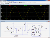
For those willing to play, here is the sim file: you have to move the jumpers according to the table on the left, and read the corresponding parameter on the suitable arb source. In the screenshot example, the ESR value (10Ω) is extracted.
The 4069/4066 combo's emulate the 4053, you can use directly a 4053 if you find a suitable model, or use the native switches from LTspice
-One is fundamental/theoretical: the type of capacitances it measures (theoretical, energy and bypass) have no official existence, they are my own pet definitions, and I am probably the only person finding them of interest.
-The other is more practical: I have built this meter using my stock of parts, and this includes a 5 position, 5 deck, 10 circuits selector, something that is probably not easy to source nowadays.
However, the principles and circuits are sound and robust, and they can be reused in many other personal interpretations/implementations.
Back to the acquisition circuit:
It is essentially a vector computer: the two channels, voltage and current across/through the capacitor are amplified and/or quadrature shifted, scaled, have a synchronization signal extracted and are vectorially demodulated in synchronous detectors.
The resulting signals are then ready to be arithmetically processed by the A to D converter.
The circuit is capable of computing basically any quantity: if you combine the 4 possibilities of Quadrature/In phase inputs, the 4 possibilities of sync signal to demodulate them, the 4 ways to apply them to the ADC (I to in or to ref, V to in or to ref, constant on either of the inputs), you end up with 64 displayable quantities, to which you can still add some direct phase options.
Not all of these quantities have an interest or even a physical meaning, but you still have a good choice of what to extract.
I have selected five of them, but as I said, it is a matter of personal taste (and the number of ways of the selector!).
The source of stimulus is a 0.4V AC direct from the mains transformer: I have used a 20VA toroid that I have partially rewound. The stimulus winding has 4 turns of 6mm² wire, and has a resistance <1.5mΩ.
When I designed the thing, I made a bet: that the heavily distorted mains waveform would cause no major issues, thanks to the synchronous demodulation. Was I right in my assumption? Well sort of, but more on this later....
All the circuit is based on very cheap, common and easily substitutable commodity ICs, and yet is practically adjusment-free: that is the beauty of the synchronous demodulation.
For those willing to play, here is the sim file: you have to move the jumpers according to the table on the left, and read the corresponding parameter on the suitable arb source. In the screenshot example, the ESR value (10Ω) is extracted.
The 4069/4066 combo's emulate the 4053, you can use directly a 4053 if you find a suitable model, or use the native switches from LTspice
Attachments
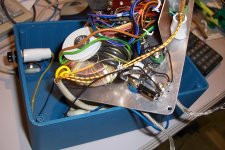
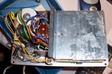
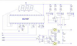
Here is the rest of the circuit: ADC, display and power supply.
A word about the choice of 0.4V/50Hz as a source of stimulus:
I wanted to make the test at a realistic current level, and exercise the reactive character of the capacitor tested, ie. evaluate its energy storage ability.
To do that, it is necessary to subject the CUT to a significant reactive power: current and voltage simultaneously, to maximize their product.
This could only be done at a low frequency: with capacitors in this range of values, higher frequencies combined with a significant voltage would result in impossibly high currents.
Anyway, contrary to a widespread belief, low frequencies provide a much better insight into the properties of an E-lytic than higher ones, and they are also more testing: an indication of that is the ripple current rating: it is significantly lower at low frequencies.
Common ESR-meters (or pseudo-ESR meters) often operate at insanely high frequencies (and they generally measure the magnitude of the global impedance, not actually its resistive component). This means that they do not actually test the "capacitive" ability of a capacitor, but rather its shunting, or bypassing ability.
In addition, if a capacitor is already partially damaged, the remaining "wet zones" may suffice to provide a "good" indication.
At 50Hz, if part of the capacity is missing, it will show immediately, even if the wet zones left have a low series resistance.
The relatively low test voltage is also required for another reason than keeping the current within reasonable limits: the test is made in the absence of bias, meaning that the CUT will see a reverse voltage.
A reverse voltage is acceptable under certain conditions: if it is <1V, for short durations and at normal ambient temperatures (~25°C).
Here, we are on the safe side: the voltage is <600mV^ (470mV^ for my prototype) and it reverses periodically. Even the lowest voltage, most delicate tantalum cap is able to tolerate that.
Why no bias? Initially, I had intended to provide one, but I changed my mind in view of the practical difficulties: it would have required a monstrously large blocking cap, larger than the complete tester itself.
Note that the bias level may have an influence on the performances, but it is much less marked than the current level: I have noticed that some capacitors, when left unused for a very long period of time (>10 years) develop a high series resistance.
However, this condition is easily reversible: a few minutes of moderate bias (much lower than the working voltage) is sufficient to restore the characteristics. There is therefore no real practical need for such a bias.
Operating at a low voltage has another benefit: it allows in-circuit testing.
In the case of my prototype, paralleling the CUT with a big silicon rectifier diode changes nothing to the measured parameters.
Even a schottky diode degrades the accuracy only very moderately.
Attachments
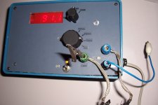
- I am now going to describe the functions I have implemented on my prototype.
Initially, the acquisition core was going to be hardwired in a single configuration, Cenergy, the most pertinent for what I had in mind.
Cenergy is a measure of the ability of the capacitor to store and release energy immediately. It represents the capacitance directly available at the capacitor's terminals.
I later realized that in fact, this capacitance is the same as the one in the parallel model, but this does not detract from its usefulness in the power/energy domain.
Then, I thought it was a pity to have such a nice acquisition circuit, and use only less than 5% of its potential.
I defined another type of capacitance, Cbypass, and added it to the measured parameters.
Cbypass is a purely artificial figure: basically, it is not even a capacitance, it is an admittance, arithmetically manipulated to be expressed in capacitance units.
Essentially, the magnitude of the impedance presented by the capacitor is converted into a pure capacitance having the same reactance.
It measures the ability of the component to shunt away ripple and other disturbances.
This is useful in particular for large capacitors, where the series resistance is a significant portion of the impedance. For example, a 10,000µF has a reactance of 320mΩ at 50Hz. If its series resistance is also 320mΩ, the resulting impedance will be √2*320=450mΩ, resulting in Cbypass of 7,000µF.
I also added the ESR, since it is a commonly used parameter. In this case, it actually is the ESR, and not some non-vector substitute: for example, if you add a parallel resistor to the CUT, you see its ESR increase, a bit counter-intuitively.
At that stage, I had 3 functions, but the suitable rotary switch having enough circuits I had found had 5 positions. I could have left two them unused, but I preferred to add two more functions: one is Ctheoretical, which is simply the value of capacitance in the series representation, the one that is generally considered as the nominal value, and δ, like in tan δ.
- Why not tan δ?
δ is directly available in PWM form, and it carries the same information as the tangent.
For small angles (in radians), tan δ=~δ, but here with E-lytics, sometimes in a poor condition, such an approximation is not tenable, which is why I formatted the angle in degrees.
The resolution is only 0.1°, because a resolution of 0.01° would have limited the range to 20°, which would be too small for some capacitors.
There is a similar issue for ESR: for example, in the 20µF range, a full scale value of 200Ω would have been OK (the reactance of a 20µF is 160Ω).
But the 20µF range has to be used for smaller capacitors too, down to 2µF, and a maximum of 200Ω would have been too small for many capacitors, which is why the ESR scale corresponding to 20µF was increased to 2000Ω.
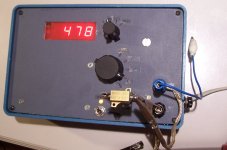
The acquisition engine could compute many other parameters, not even limited to capacitors: in the pic below, it is shown measuring a pure 0.47Ω resistor in ESR mode.
With a different configuration, it could also measure inductors for example.
I didn't implement it, because I have no need to measure inductors at 50Hz, but it is perfectly possible too.
Attachments
Common ESR-meters (or pseudo-ESR meters) often operate at insanely high frequencies (and they generally measure the magnitude of the global impedance, not actually its resistive component).
You seem like a car with no tires for rain and who also does not care to read either the weather report prior getting out in the street.
Capacitors testing process is an instruction offered by the manufacturer according its type of capacitor and it very special characteristics.
This is the way that they are tested in the factory prior be shipped, and you need also to test them according the same standards and under the same testing environment so to confirm their specifications.
Today I can by-pass completely the theory of your design by feeding one capacitor at it max rated voltage for few minutes prior inspecting it with an 2012 or fresher produced (by a test and measurement company) portable LCR meter.
By such a capacitor testing method, the capacitor will be measured when it would have stabilize it internal temperature and chemistry.
I am friend of DIY but never underestimate the tools coming for much more reliable sources which have much more specialized equipment when they need to confirm an new theory.
I will not comment, and let other members form their own opinion about your interesting and valuable contribution...You seem like a car with no tires for rain and who also does not care to read either the weather report prior getting out in the street.
snip .../... snip
I am friend of DIY but never underestimate the tools coming for much more reliable sources which have much more specialized equipment when they need to confirm an new theory.
Now, let us tackle another contentious issue:
Was I right?When I designed the thing, I made a bet: that the heavily distorted mains waveform would cause no major issues, thanks to the synchronous demodulation. Was I right in my assumption? Well sort of, but more on this later....
Regarding the capacitance calibers, yes: the quality of the stimulus is practically unimportant, thanks to the ratiometric measurement principle eliminating amplitude issues, and thanks to the synchronous demodulation which is relatively insensitive to perturbing signals.
However, for ESR and δ, things are somewhat different: a weak quadrature component has to be extracted from a large signal, making the process much more sensitive to noise and distortions.
In fact, these functions were completely unusable, the values were all over the place.
I did not want to abandon these functions now that they had been implemented, and this meant filtering, filtering, filtering.
A conventional, passive filter was not realistically feasible, it would have had to remove frequencies as low as 150Hz without affecting the 50Hz, and at the same time fit into the existing box: impossible.
I had to improvise a high performance active filter.
I came up with two solutions: one open-loop, and the other closed-loop.
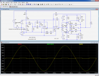
The screenshot below outlines the operation of the open-loop version:
The red trace is the polluted mains signal.
A bandpass filter extracts the 50Hz fundamental and applies it to a bridge of resistors subtracting the residue from the mains waveform.
The result is accurately amplified and scaled (yellow trace), and applied in series with the transformer's primary, resulting in a cleaned-up waveform (green).
Attachments
Now, let us tackle another contentious issue:
Sorry mate I did not see that you are that many.

The closed-loop version of the active filter looks superficially the same as the open-loop one, except that the subtracting bridge is replaced by an auxiliary feedback winding of the transformer, L2.
The operation looks similar, see below.
There are differences though: the requirement of accurate matching of the bridge resistors disappears, but now the system works in closed loop, and has to fulfill stability conditions, and it requires an additional winding, of course.
What could be the benefits of this version, compared to the other one? After all, they both manage to eliminate completely the disturbances.
The closed-loop filter includes the transformer in the loop, and also takes cares of unwanted harmonics generated at that level. This could be the transformer itself, if it is driven into saturation for example, but also any load it drives and happens to be non-linear.
This is an important point, as we will see...
Attachments
- Initially, I had opted for the open-loop version of the electronic filter: mostly because it didn't require an additional (isolated) winding, and also to dodge possible closed-loop issues.
And, guess what?
It didn't work quite as intended: the primary waveform was spotless, but the stimulus waveform was slightly corrupted: the primary series impedance (copper + leakage inductance) was sufficient to couple the distortion induced by the rectifier and capacitors feeding the rest of the circuit.
I was aware of the possibility of a problem there, but since the transformer's 20VA were widely overdimensioned compared to the 1 or 2 watt used by the meter, I had figured I could go away with it.
Not so: I had to modify the circuit and wind the 40 or so turns of Tefzel wire of the feedback winding.
When it was done, everything worked as intended, fortunately.
- Note that the electronic filter could be used on its own: it is perfectly capable of cleaning up the supply of sensitive devices, I am thinking of preamplifiers and TT motors for example: compared to a conventional passive filter, it is much more effective and works for any frequency, including very low ones. An induction motor, synchronous or asynchronous runs much more smoothly when fed by a perfect sinewave.
For that kind of use, the open loop version would have to be chosen: it is "agnostic", and does not require modifications to the supplied device, like an awkward isolated winding.
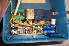
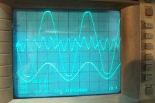
In my case, the output amplifier of the filter has a capability of 2~3W, and a maximum peak voltage of ~40V: a little more than 10% of the mains voltage, which should be sufficient for "normal" situations: the oscillogram shows the real life operation of the circuit.
The large, distorted waveform is my raw incoming mains, the jagged waveform is the error voltage at the output of the amplifier, and the clean sinewave is the corrected, cleaned-up stimulus voltage.
The whole circuit is fed by a capacitive supply. The capacitive current has to be slightly larger than the maximum intended supplied current, to account for the losses.
It is thus obvious that the whole circuit is electrically connected to the mains, and adequate precautions have to be taken to avoid accidental contact with the secondary side, exposed parts, and during test: if measurements have to be made, an isolation transformer is essential.
Be sure to understand what it means to work with lethal voltages before you attempt building such a circuit.
Also note that "X"-rated capacitors are not an option or a luxury for this kind of application: they are essential for safety.
In this case, the circuit is used solely to eliminate harmonics (and more generally, anything that isn't 50Hz), but it could also cumulate other functions, like bucking or boosting the voltage, or even regulating it: to do that you just need to feed the BP filter with a limited, constant amplitude 50Hz. Of course, this will require more operating headroom than for just filtering, meaning the supplies will have to be pushed to +/-60V or 80V.
A fascinating possibility if the circuit is used for bucking only, is to make it self-feeding: the output transistors will work as synchronous rectifiers, possibly helped by the start-up/protection diodes D3 D4....
The capacitive supply would then become redundant....
Attachments
Last edited:
- To close the subject, here is some additional information:
It is obvious that this instrument is not a general-purpose capacitance-meter.
The special measurement conditions yield information not available with other types of meters, even the best professional RLC meters, and it can differentiate between two nominally identical capacitors.
I had the need for such an instrument for reasons that are difficult to explain on a public forum, and other people may also find it useful, but it certainly should not be your first or sole capacitance-meter, it is too specialized for that.
A good thing is that it can be configured to extract exactly the parameter you need, under heavy stress conditions. It can be simplified into a single-purpose tester, implemented with a microcontroller, analog switches etc: that's up to you.
- A word about the calibration philosophy:
What I did was to tweak the theoretical components values in simulation, thus performing a software pre-calibration, and then hand picked the components to 0.1%.
This leaves just one master calibration control AJ1 for the finalization of all functions and calibers.
This is possible, because it influences all the ranges at the same time.
It should be adjusted in the conditions where you are going to need the most accuracy: it could be the ESR, or one of the capacitance mode, probably Ct, because it allows an easy correlation with other measurement methods and instruments.
AJ2 adjusts the offset of the variable gain amplifier.
Select the lowest range, "2", no capacitor connected and adjust to get 0V DC at the output of U3. If you use a more modern, trimmed opamp this adjustment is not required.
AJ3 has to be adjusted in δ mode: connect a low-loss capacitor (polypropylene) and adjust AJ3 to read ~0°.
The ratiometric/vector type of operation makes the meter insensitive to the absolute value of the stimulus, and other values can be adopted.
For example, if you need to make in-circuit measurements in the presence of large schottky diodes, you could lower the voltage without major inconvenient.
If it is reduced too much, S/N issues will begin to show, but 100mV AC is certainly possible.
For capacitance ranges, the quality of the stimulus is not important, but if you need ESR or δ, you have to be prepared to implement the electronic filter option.
If you use a common transformer for the stimulus and DC power supply, it will have to be the closed-loop version and its custom winding.
Normally, the theoretical value of capacitance is the largest and the energy value is the smallest with Cbypass in-between, but there are some exceptions: the internal phenomenon/structure of E-caps can be more complex than their usual equivalent circuit.
I have not made a 4-wire implementation outside of the box, choosing instead short/heavy gauge test-leads: I sacrificed some of the accuracy for simplicity and ease of use, but it would be perfectly possible to build a full 6-wire version.
- Adjustment of the electronic filter:
Connect the voltmeter between the local reference (mid-supply of the opamps) and the output of U1; adjust AJ2 for a maximum reading.
Connect the voltmeter between the local reference and the output of the power amplifier; adjust AJ1 for a minimum reading. Readjust AJ2 to minimize further and come back to AJ1 until there is no more change.
Last edited:
- Status
- This old topic is closed. If you want to reopen this topic, contact a moderator using the "Report Post" button.
- Home
- Design & Build
- Equipment & Tools
- Power-oriented cap-meter