Hello and happy new year to everyone ") .
.
Frex, thank you for the update and the fast progress of this project.
Indeed, the parts you are mentioned are usually the most difficult/expensive.
I think it will be easy to achieve a target of 25 pieces for a so usefull & interesting project.
TQFP-144 package? A soldering nightmare.
P.S. There are no words that can be said for these tragic events that happened in your country...
.Frex, thank you for the update and the fast progress of this project.
Indeed, the parts you are mentioned are usually the most difficult/expensive.
I think it will be easy to achieve a target of 25 pieces for a so usefull & interesting project.
TQFP-144 package? A soldering nightmare
.P.S. There are no words that can be said for these tragic events that happened in your country...
Hello everyone,
Frex, I repeat that is a great project, but I can't understand why didn't you use a microcontroller instead of a CPLD.
It shouldn't be so difficult, and an MCU will cost about the half of the CPLD. I don't see any big disadvantages.
Maybe this White Paper clarify the choice to use CPLD
Six Ways to Replace a Microcontroller With a CPLD
http://www.altera.com/literature/wp/wp-01041-six-ways-to-replace-microcontroller-with-cpld.pdf
Maybe this White Paper clarify the choice to use CPLD
Six Ways to Replace a Microcontroller With a CPLD
http://www.altera.com/literature/wp/wp-01041-six-ways-to-replace-microcontroller-with-cpld.pdf
Interesting topic, however, more or less, it seems that μC or CPLD is a case by case choice.
Bonjour Frex,
Yes not a good start to the year there If only I could read french, I would read Charlie Hebdo for sure.
Just wanted to say, that I find your project very interesting, and your work quite impressive!
Alas, I don't have the knowledge to contribute in development, but might well build one, if PCB or kit becomes available at some point..
Yes not a good start to the year there
If only I could read french, I would read Charlie Hebdo for sure. Just wanted to say, that I find your project very interesting, and your work quite impressive!
Alas, I don't have the knowledge to contribute in development, but might well build one, if PCB or kit becomes available at some point..
Hello all and thank you for your comments.
Bex83, to be honest with you, the main reason why i use CPLD instead of uC is that because i am really more comfortable with CPLD design !
I don't know the white paper linked by Carpin, but i agree with that, CPDL are now very capable, and are sometimes a better way than uC, especially when many real time process must be made. So i must probably learn programming uC a days !
Frex
Frex, I agree with you. In some cases, CPLDs are the best solution, but in this case probably not. But there are more ways to reach the target, and your solution seems to do it. Bigger problems should be soldering the big ic (as written) and the difficult for most diyer to modify the logic for example to use an lcd display instead of 7seg. Using a Pic or Avr it would be easier for most people.
EPSUX3V2 Beta1 schematic release
Hello all,
Good news, the first Beta release of the schematic is ready to be published.
Probably some modifications will occur before to start the circuit board drawing, but normally only minor changes.
You can download the full EPSUX3V2.00 Beta 1 schematics HERE (~1Mo).
For better design comprehension, as reminder you can also download ;
This week, i worked to test the dual current mirror sources that drive the current
limit of LT3081. Works fine.
Some parts i plan to use in the design has been already purchased in order to check it in real world (switches and connectors).
I must check very fast if all parts are able to be integrated in the target enclosure (Hammond 1455N2201).
I start the mechanical design of the PSU, front and rear panel design.
To follow....
Frex
Hello all,
Good news, the first Beta release of the schematic is ready to be published.
Probably some modifications will occur before to start the circuit board drawing, but normally only minor changes.
You can download the full EPSUX3V2.00 Beta 1 schematics HERE (~1Mo).
For better design comprehension, as reminder you can also download ;
- The EPSUX3v2 full synoptic (pdf file, 100ko).
- The EPSUX3v2 DC/DC combo regulator block synoptic (pdf file, 100ko).
This week, i worked to test the dual current mirror sources that drive the current
limit of LT3081. Works fine.
Some parts i plan to use in the design has been already purchased in order to check it in real world (switches and connectors).
I must check very fast if all parts are able to be integrated in the target enclosure (Hammond 1455N2201).
I start the mechanical design of the PSU, front and rear panel design.
To follow....
Frex
Hello Frex, can you explain more datails about magnetic parts? For example which core used for the xformer, what parts are input filter and PFC inductors..
how did you find the actual switching frequency, doing a lot of tests and choosing the freq with best result?
A small possible error in the schematic: R65 maybe should be 17.4K as the other channels.
Thank you.
how did you find the actual switching frequency, doing a lot of tests and choosing the freq with best result?
A small possible error in the schematic: R65 maybe should be 17.4K as the other channels.
Thank you.
Hello Bex83,
The magnetics parts has already been designed and build as you can see on the prototype board here (some posts ago).
They won't change for the final design.
For the PFC inductor, it's a PQ26/20 core(98 material from Faire-Rite), and for the LLC transformer it's a PQ32/30 in 3C95 material.
The input Power Factor Corrector (PFC) boost stage work at a fixed frequency of 133 kHz (slightly below the starting frequency of 150kHz for conducted EMI test).
The LLC nominal resonant frequency is 120kHz.
As LLC work, the switching frequency change a little to regulate the output voltage.
You can see on previous posts many measurements made on the PFC and LLC.
About the value of R65, you are right, there is a mistake.I must check carefully each value. This is why it's a good thing that not only my eyes read the schematics, thank you !
Regards.
Frex
Hello rikkitikkitavi (funny name!),
I use a PQ bobbin where i add an thin epoxy splitter to separate physically primary and secondary windings. Each of them are made with Litz wire to avoid copper loss at working frequency (~120kHz).
A small number of turns are needed, so it's easy to do. The winding splitting is necessary to get a high primary leakage inductance that allow LLC to work (in others SMPS topology we must avoid this leakage !).
Regards.
Frex
Last edited:
Hello rikkitikkitavi,
With a concentric winding you will get low leakage inductance that we need, and you will also need to add some insulated tape to get a good insulation.
Separate each winding in LLC core allow easy insulation and good reproducibility of the leakage.
In addition, the parasitic capacitor between primary and secondary is much lower that is an advantage
for EMC compliance.
Regards.
Frex
Hello all,
Good news, the first Beta release of the schematic is ready to be published.
Probably some modifications will occur before to start the circuit board drawing, but normally only minor changes.
You can download the full EPSUX3V2.00 Beta 1 schematics HERE (~1Mo).
For better design comprehension, as reminder you can also download ;
- The EPSUX3v2 full synoptic (pdf file, 100ko).
- The EPSUX3v2 DC/DC combo regulator block synoptic (pdf file, 100ko).
This week, i worked to test the dual current mirror sources that drive the current
limit of LT3081. Works fine.
Some parts i plan to use in the design has been already purchased in order to check it in real world (switches and connectors).
I must check very fast if all parts are able to be integrated in the target enclosure (Hammond 1455N2201).
I start the mechanical design of the PSU, front and rear panel design.
To follow....
Frex
Hi Frex, I'm looking in this new schematic. Excellent job! I'm wondering how are you satisfied with TPS54540? It looks really amazing that it can deliver up to 5A without using external switch. It's not appropriate for my design since I'd like to go with Vout of up to 50V but it's interesting to know how such devices are performing in real world.
I'm also would like to hear about your experience with PNP tracker circuit. Did you notice any instability trying it with different loads and Vout? Do you possibly have any experience with optocoupler settings such as on presented in LTC's document AN32 - High Efficiency Linear Regulators (see pg.5)?
Hello,
Thank you Prasimix. Yours is also a very complete design work.
I already used the TPS5450 (grand brother) but first time the TPS54540.
The only difference is that 54540 can work at higher frequency and allow eco-mode operation.
The TPS5450 work fine even at high current, but care must be taken about output ripple and noise.
The 54540 seems a better choice. At higher operating frequency and same output inductor you get a lower ripple.
All must be made to ensure that switching noise doesn't ends up on the output.
(This is why for example you find a LC filter between the buck and the LT3081 regulator).
Also, in these type a design, components placement and routing are equally important that the schematic itself !
I love LT app notes...Always a very good source of inspiration and imagination and sometimes what we can do with parts not made for !
I don't have experience on PNP tracker, but the schematics seems interesting and not very difficult to build.
Probably the better way would be to try to build it in a small "on the fly" circuit board and evaluate what it give ?
If you search how to control the voltage of the pre-regulator, did you have read the
LT article on which my design is based ?
Regards.
Frex
Thank you Prasimix. Yours is also a very complete design work
.I already used the TPS5450 (grand brother) but first time the TPS54540.
The only difference is that 54540 can work at higher frequency and allow eco-mode operation.
The TPS5450 work fine even at high current, but care must be taken about output ripple and noise.
The 54540 seems a better choice. At higher operating frequency and same output inductor you get a lower ripple.
All must be made to ensure that switching noise doesn't ends up on the output.
(This is why for example you find a LC filter between the buck and the LT3081 regulator).
Also, in these type a design, components placement and routing are equally important that the schematic itself !
I love LT app notes...Always a very good source of inspiration and imagination and sometimes what we can do with parts not made for !
I don't have experience on PNP tracker, but the schematics seems interesting and not very difficult to build.
Probably the better way would be to try to build it in a small "on the fly" circuit board and evaluate what it give ?
If you search how to control the voltage of the pre-regulator, did you have read the
LT article on which my design is based ?
Regards.
Frex
Project progress...
Hello all,
The EPSUX3 lab power supply project is currently in good progress.
I receive in next week all parts that have impact in mechanical design.
I've worked on the front and rear panel design, how i can do it and for what cost.
Two solutions are possible, the same engraved aluminum panels like EPSUX3V1
(you can see how it looks in page 1 of this thread), and panels made in circuit board.
Yes, in circuit board ! (thanks to TheShaman for his link !).
The main advantage is that it allow much lower cost for medium batch (~25 pieces).
It's possible to use white solder-mask with black silkscreen, all holes can already be done, and the overall appearance is very good.
I try also to reduce the price of aluminum panels using simplest drilling and less marking.I try also to ask some quotation.
For now, all door are open...
I have also start component placement in circuit board design. I will post a picture
when all parts will be "in" the board space (if it goes in !).
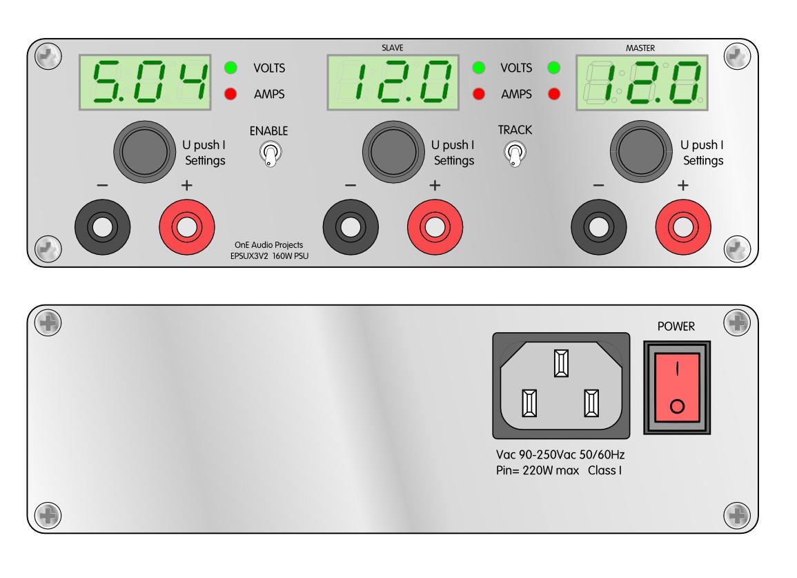
You can see below panels drawing preview, with markings.
I hope that you will find that clear and smart
Regards.
Frex
Hello all,
The EPSUX3 lab power supply project is currently in good progress.
I receive in next week all parts that have impact in mechanical design.
I've worked on the front and rear panel design, how i can do it and for what cost.
Two solutions are possible, the same engraved aluminum panels like EPSUX3V1
(you can see how it looks in page 1 of this thread), and panels made in circuit board.
Yes, in circuit board ! (thanks to TheShaman for his link !).
The main advantage is that it allow much lower cost for medium batch (~25 pieces).
It's possible to use white solder-mask with black silkscreen, all holes can already be done, and the overall appearance is very good.
I try also to reduce the price of aluminum panels using simplest drilling and less marking.I try also to ask some quotation.
For now, all door are open...
I have also start component placement in circuit board design. I will post a picture
when all parts will be "in" the board space (if it goes in !).
You can see below panels drawing preview, with markings.
I hope that you will find that clear and smart
Regards.
Frex
...and panels made in circuit board.
Yes, in circuit board ! (thanks to TheShaman for his link !).
No worries, thanks to AKN really.
This is where it was first linked.
PSU looks good. Sign me up!
- Home
- Design & Build
- Equipment & Tools
- Triple outputs 160W Lab PSU -- EPSUX3 version 2 !