Real time crossover evaluation can be tedious and time consuming, however, an L/C substitution unit should address some of these issues.
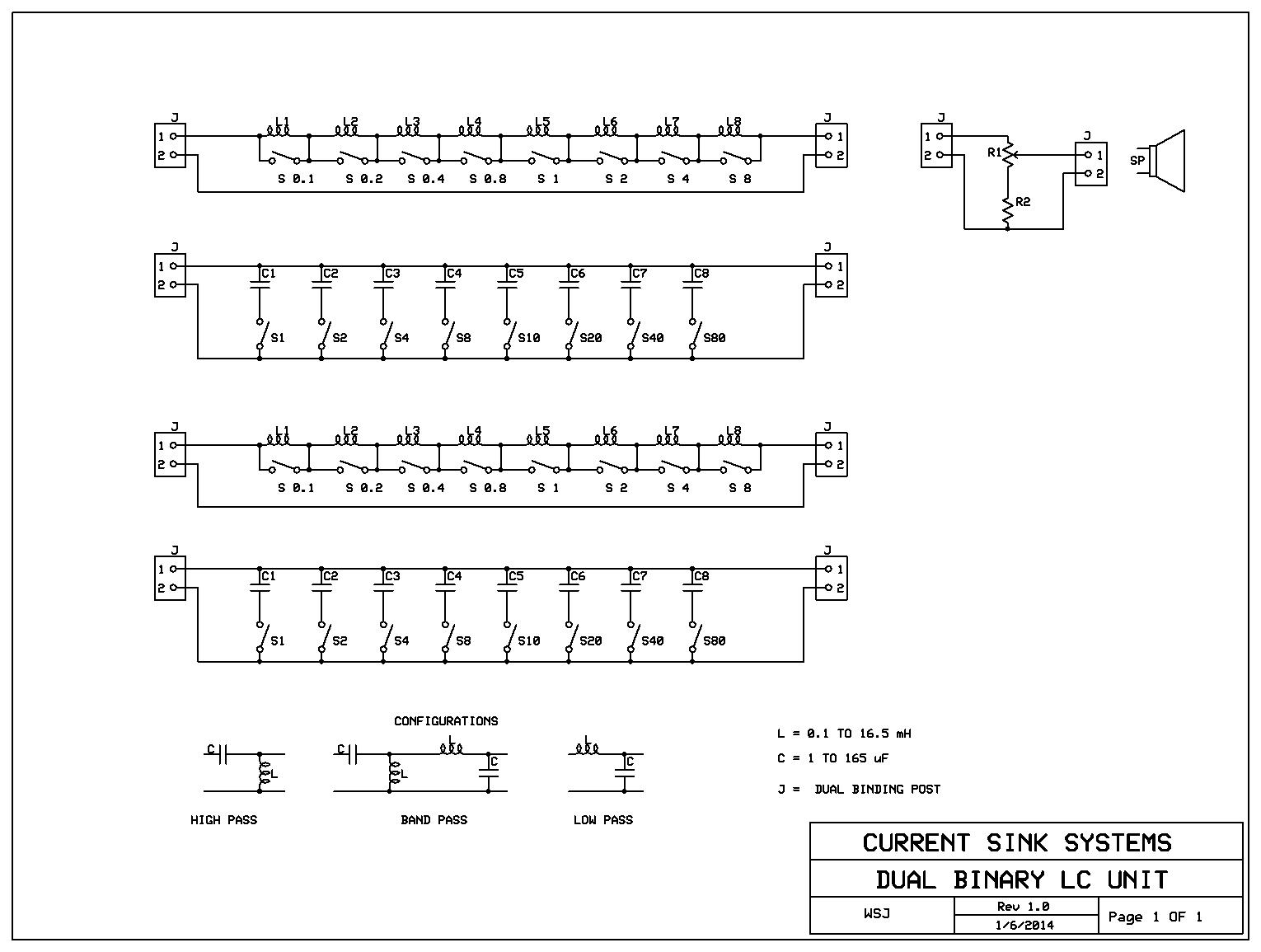
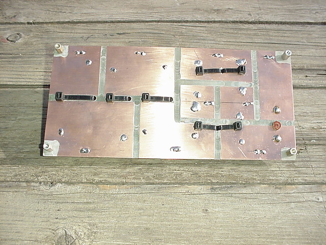
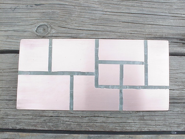
The advantage of a binary L/C substitution unit is to allow the maximum number of values with a practical number of components. This design can be configured to provide HP, BP or LP 2nd order filters for evaluation in real time. The unit incorporates two capacitor sections and two inductor sections that can be configured with banana cables. The capacitance range is 1 to 165 uF in 1 uF increments and the inductance range is 0.1 to 16.5 mH in 0.1 mH increments.
Any recommendations for crossover design programs?
Please let me know what you think and what improvements or corrections could be made.
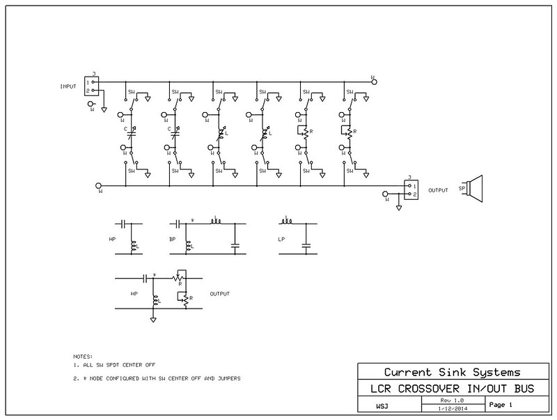
This is the input/output bus schematic.
The advantage of a binary L/C substitution unit is to allow the maximum number of values with a practical number of components. This design can be configured to provide HP, BP or LP 2nd order filters for evaluation in real time. The unit incorporates two capacitor sections and two inductor sections that can be configured with banana cables. The capacitance range is 1 to 165 uF in 1 uF increments and the inductance range is 0.1 to 16.5 mH in 0.1 mH increments.
Any recommendations for crossover design programs?
Please let me know what you think and what improvements or corrections could be made.
This is the input/output bus schematic.
Last edited:
Very soon you will realize crossovers have a LOT more parts in them. You could make several sets of course. Some for the crossovers, some for serial and parallel filters, Zobels etc. You will need several of each resistor from 1 to 12 or so as well.
I have resigned to a big box of values and a pile of jumper cables. As things get closer, I switch to euro-style terminal strips cut into small chunks. Closer still, I tack solder things.
If you use a tool like PSD Lite, and measure well, you will see that the amount of final tweaking is greatly cut down. It is always clumsy.
Very soon you will realize crossovers have a LOT more parts in them. You could make several sets of course. Some for the crossovers, some for serial and parallel filters, Zobels etc. You will need several of each resistor from 1 to 12 or so as well.
I have resigned to a big box of values and a pile of jumper cables. As things get closer, I switch to euro-style terminal strips cut into small chunks. Closer still, I tack solder things.
If you use a tool like PSD Lite, and measure well, you will see that the amount of final tweaking is greatly cut down. It is always clumsy.
I have a large enclosure for the project.
Additional sections will include 1-16 ohms, for the crossover.
1-16 ohms, at 100 Watts for Loads, with fan.
Also a sound card protection network.
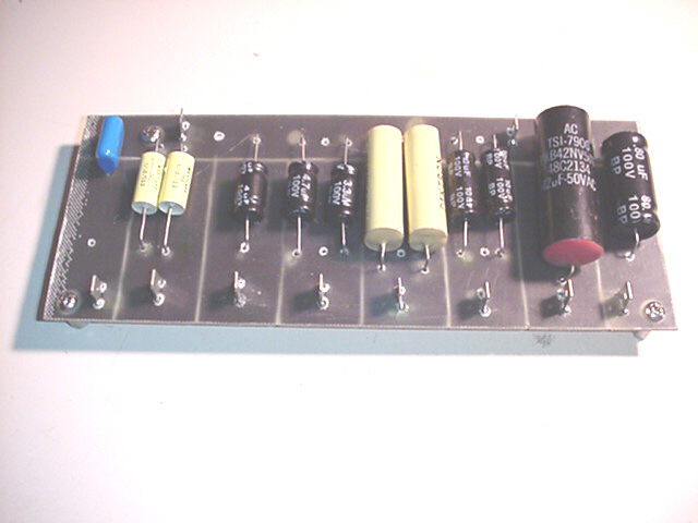
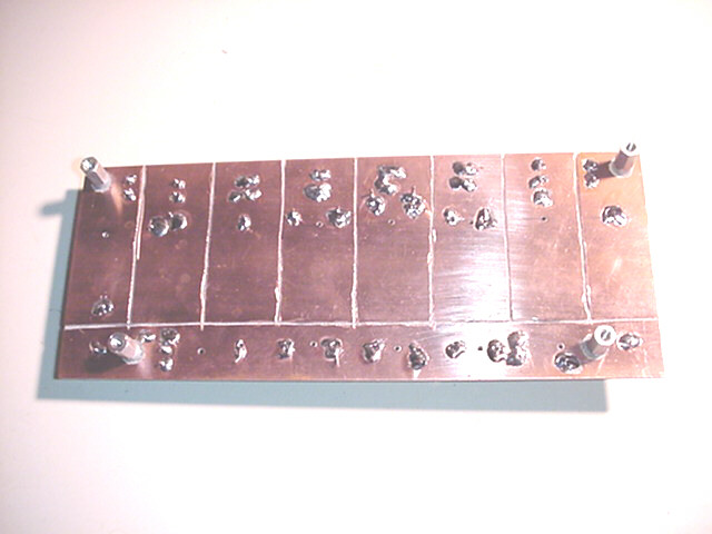
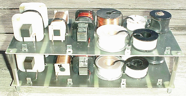
This is the inductor board; the cuts were made with a small trim router.


Plus and minus mutual coupling issues. Still, you need a LOT more sets of parts. I get the impression you believe you can use textbook filters only and am not thinking about the tweaks necessary for decent response. Please, download something like PSD lite and look at the options he gives you.
Depending on driver quality, a simple 2-way 3rd order electric crossover for ill-behaved drivers can have upwards of a dozen components. I have modeled at 16 ( then tossed out the drivers as too hard to use junk.) When you get to final voicing, you need two sets.
I would build my load box separate, It is for amp stability testing, not for crossover tweaking. My load plate is made of 4 2-Ohm 50 Watt'ers. They are inductive wound which is actually better for an amp. For stability and distortion testing, you really need to go to active loads where you can control the complex impedance. The famous load cube concept. Don't take my word for it, go model it is SPICE. You may be surprised what happens at clipping into a reactive load.
Plus and minus mutual coupling issues.
Do you mean the inductors are too close together? Each inductor value is about 1% after tweaking the windings, but the total inductance is 13% high.
Still, you need a LOT more sets of parts. I get the impression you believe you can use textbook filters only and am not thinking about the tweaks necessary for decent response. Please, download something like PSD lite and look at the options he gives you.
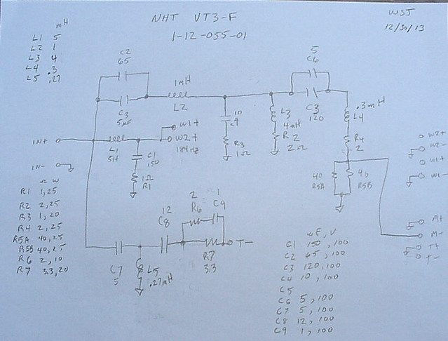
I traced the circuit of a few NHT crossovers, this one about 20 parts for a 3 way system. I have some of the midrange drivers from this system and parameters, I realize the enclosure has an effect on the characters. I just started looking at PSD lite.
I would build my load box separate, It is for amp stability testing, not for crossover tweaking. My load plate is made of 4 2-Ohm 50 Watt'ers. They are inductive wound which is actually better for an amp.
That sounds good, I have several 50 W. 2 Ω which can make a binary weighted load 1, 2, 4, 8.
Thank you.
Wayne
Looking at NHT should be a good help. They use pretty fair drivers and overall do pretty well with them; better than many big name higher priced companies. Look up an LS3-5A crossover.
It is not just that the inductors are close, but they are parallel. If you only used one at a time, it might not matter, but two at a time it does. If they are used in different parts of the circuit, ugly things can happen.
Enclosures have a LOT of effect. The obvious is the T/S tuning, but after that you get into all the baffle size and shape issues. While pulling in free software, grab the Edge for diffraction simulation. I don't get too wrapped up in magic materials, but I can't explain enough times what doing a 3/4 inch roundover on all 12 sides can do for top end smoothness. It takes a brittle over bright metal dome and makes it clean and detailed. ( provided it is a decent one to begin with)
I also have a habit of documenting in LTSpice my crossovers so I can keep their independent transfer functions in my mind. It does not tell you what will happen in the circuit, but helps me when I get confused.
Hi,
Its very old school and gets nowhere near the possible
complexities of crossovers. Simulation is far better.
Measurements and simulation even better.
Such things have no place in modern speaker design.
rgds, sreten.
What measurements are you talking about?
Looking at NHT should be a good help. They use pretty fair drivers and overall do pretty well with them; better than many big name higher priced companies. Look up an LS3-5A crossover.
It is not just that the inductors are close, but they are parallel. If you only used one at a time, it might not matter, but two at a time it does. If they are used in different parts of the circuit, ugly things can happen.
Enclosures have a LOT of effect. The obvious is the T/S tuning, but after that you get into all the baffle size and shape issues. While pulling in free software, grab the Edge for diffraction simulation. I don't get too wrapped up in magic materials, but I can't explain enough times what doing a 3/4 inch roundover on all 12 sides can do for top end smoothness. It takes a brittle over bright metal dome and makes it clean and detailed. ( provided it is a decent one to begin with)
I also have a habit of documenting in LTSpice my crossovers so I can keep their independent transfer functions in my mind. It does not tell you what will happen in the circuit, but helps me when I get confused.
What is the effect of placing a resistor across an inductor?
Hi,
Its very old school and gets nowhere near the possible
complexities of crossovers. Simulation is far better.
Measurements and simulation even better.
Such things have no place in modern speaker design.
rgds, sreten.
How can a simulation take into account unknown speaker parameters much less room acoustics? I have several experimental speakers with no part numbers or known parameters. What actually matters to me, is the acoustic output from the drivers in my listening room.
You could also build the model load Bob Cordell suggests ( fig 15.5, P 321).
I use it in Spice as a vague stab at a real load.
I have the real load mounted in an enclosure with three sets of driver wires coming out the rear ready for the crossover testing. For acoustic measurements I use REW software with an EMM-6 Electret Measurement Microphone, EMU 0204 and a Hafler XL-280. I'm doing this project for fun.
Thank you for taking the time to respond to my post.
Last edited:
I see inductor cross-coupling everywhere.
I will not stack them and mount them with about 5" between the boards. The 8, 4 and 2 mH have some interaction, the 8 mH may not be use with the 4 or 2 mH. I should have found a larger box to allow more spacing. If turns out to be a problem, I have enough space to make 16" x 6" boards and mount them with some space between each board.
I have the real load mounted in an enclosure with three sets of driver wires coming out the rear ready for the crossover testing. For acoustic measurements I use REW software with an EMM-6 Electret Measurement Microphone, EMU 0204 and a Hafler XL-280. I'm doing this project for fun.
Thank you for taking the time to respond to my post.
What I was suggesting is you are really building tools for two different functions. The first to make swapping parts for crossover tweaking easier, the second was the power load for amp testing. It was in that I suggest putting in an additional representative load. Maybe with a switchable horrible additional capacitance.
If we all were not doing this for fun, we would all be crazy. Or is it the other way around?
I agree the high power loads should be in a second box. I plan to include lower power resistors in the L/C/R box for use within the filter networks. I will make changes to the inductor board to provide more space between inductors.
Thanks
Having built several dozen crossovers over the years, I still suggest you will be far too limited with a switch box. The good news is you need all these parts in your kit anyway.
It is not just the space. It is the orientation. When coils are parallel, their lines will interact more than when they are perpendicular to each other. If each bank is only going to be one coil in test, just knowing the actual combined value including the mutual inductance is fine. No need to change. Be very aware in the actual crossover to keep the coils perpendicular or you can get undesired actions with the HP and LP filters having mutual inductance. Play with this. Take two coils in series and put your LCR meter across them. Move them around and see the results.
I have a box I keep 6 of every value between .5 and 12 Ohms in. I try to keep several of most values between 1 and 32uF in cheap electros and as many leftovers in film as I can keep on hand. I have fewer coils as well, they are expensive.
- Status
- This old topic is closed. If you want to reopen this topic, contact a moderator using the "Report Post" button.
- Home
- Design & Build
- Equipment & Tools
- Binary L/C substitution unit for crossover evaluation