Tip I was given on my thread about protection for amps. BAS45A's. They have an order of magnitude less leakage than 1N4148 or 991's. One of then in series with a zener may make a much less obtrusive clamp. I will order a bucket full when I order the parts for the amp I am working on. There are some even better, but alas, SMT. Only testing will tell as we all know, SPICE lies.
How are you connecting the Zener? as a shunt from the signal line to GND?
If so, your problem is probably not leakage current but the soft knee of the low voltage Zener diode
P.S. Don't be frightened of SMD. It saves drilling a lot of holes!
SMD is only a problem as it does not work on perf board and I can't see things like that any more.
Yes, shunt to ground. Back to back. Many of these boxes will be damaged by more than abut 5 volts, so you need to clamp them. Maybe a string of the the diodes. Won't take too many to clamp 4 V. There are some dedicated chips that do this, but I have never had time to search them out. The knee could be a hint, but in the models the leakage seems to be an issue too. These are very high Z inputs.
Yes, shunt to ground. Back to back. Many of these boxes will be damaged by more than abut 5 volts, so you need to clamp them. Maybe a string of the the diodes. Won't take too many to clamp 4 V. There are some dedicated chips that do this, but I have never had time to search them out. The knee could be a hint, but in the models the leakage seems to be an issue too. These are very high Z inputs.
Usually best connected to the supply rails of the device. Most devices will handle .7V past the rails with no consequence and the rails are much stiffer. The current limiting resistors are also an issue, too big and you have noise. Too small and you have no protection. Magic trick- use a light bulb. Off resistance is 1/10 the on resistance. With a light pipe you could see the abuse.
Too good to be true?
After reading threads in this forum,
I started to think using my 0404 usb for audio measurement purpose.
I made a pair of TRS-TRS cables and run a RMAA loopback test.
I got these results, differ drastically from those obtained by others,
did I setup the test incorrectly?
Frequency response (from 40 Hz to 15 kHz), dB
+0.00, -0.00
Noise level, dB (A)
-149.4
Dynamic range, dB (A)
133.2
THD, %
0.0000
THD + Noise, dB (A)
-128.1
IMD + Noise, %
0.0002
Stereo crosstalk, dB
-148.5
IMD at 10 kHz, %
0.0000
Too good to be true?
Those look like digital loopback measurements. There is no way that device can deliver Noise level, dB (A) -149.4 through an analog loopback. There are specific instructions for RMAA testing with the EMU stuff somewhere. Getting meaningful reading to start with can be difficult if you have no references to check against.
Can you post more details on both the system and specific test setup and testing?
Can you post more details on both the system and specific test setup and testing?
Just to put some reality back in the test results of eMu 0404 or other typical 'sound card' measurement system ----
When I compared the accuracy of measured harmonic levels with my AP 2722 and ShibaSoku 725D, it became clear that They are not accurate below -100dB.
This is backed up other places.... John Atkinson (JA) at Stereophile did tests of 0404 also and found " 17 bit resolution".
[FYI -- the BenchMark DAC2 reaches 21 bit resolution.... according to J.A. J.A. uses the AP2722 as his reference. The BenchMark ADC might get closer to 24 bits with the use of AKM5394]
THx-RNMarsh
Last edited:
I think most are aware of this issue and that results are not comparable between DUTs/environments.
What I wonder though: Is it still a useful tool for testing performance and troubleshooting when making changes to a system? Eg, I had some issues with mains hum/interference. While the actual numbers I am measuring may not be accurate, I can still see the changes in the graphs when I make changes to grounding/shielding/cabling and use this information to help troubleshoot and improve performance. I think (and hope!) sound card measurements are still useful in this regard, to what degree though, I don't know")
What I wonder though: Is it still a useful tool for testing performance and troubleshooting when making changes to a system? Eg, I had some issues with mains hum/interference. While the actual numbers I am measuring may not be accurate, I can still see the changes in the graphs when I make changes to grounding/shielding/cabling and use this information to help troubleshoot and improve performance. I think (and hope!) sound card measurements are still useful in this regard, to what degree though, I don't know
As usual for me, I recommend "comparison" rather than absolute measurement.
If your "dodgy" measurements say 110db before the modification and 119dB after the modification and the testing methodology is identical then it is very likely that the "CHANGE" is around the 9dB ratio. It could be as little as 5dB, or as much as 15dB, but your "comparison" has measured a CHANGE!
If your "dodgy" measurements say 110db before the modification and 119dB after the modification and the testing methodology is identical then it is very likely that the "CHANGE" is around the 9dB ratio. It could be as little as 5dB, or as much as 15dB, but your "comparison" has measured a CHANGE!
It's not as good as you would get with other cards but it looks fine. You will get more accurate results if you set the FFT higher and an 'Avg' option like linear, then leave it for a few minutes.My sound card is a Creative Soundblaster.
Is this ok?
That is.It's not as good as you would get with other cards but it looks fine. You will get more accurate results if you set the FFT higher and an 'Avg' option like linear, then leave it for a few minutes.
Attachments
Last edited:
As usual for me, I recommend "comparison" rather than absolute measurement.
If your "dodgy" measurements say 110db before the modification and 119dB after the modification and the testing methodology is identical then it is very likely that the "CHANGE" is around the 9dB ratio. It could be as little as 5dB, or as much as 15dB, but your "comparison" has measured a CHANGE!
Yes, it is true and us-full this approaching.
That is.
Yes Thimio. It is better now.
Please, read the manual of ARTA about how this manages the various menus.
For example, for the THD measuring, suggests Kaiser5 or Kaiser7 with Exp Averaging (input singal -3dB).
For periodic measurements, like jitter, Floor Noise e.t.c Hanning is more acceptable.
I think you will have better measurement with 24/48 sampling.
Thanks my friend ,please take a lookYes, it is true and us-full this approaching.
Yes Thimio. It is better now.
Please, read the manual of ARTA about how this manages the various menus.
For example, for the THD measuring, suggests Kaiser5 or Kaiser7 with Exp Averaging (input singal -3dB).
For periodic measurements, like jitter, Floor Noise e.t.c Hanning is more acceptable.
I think you will have better measurement with 24/48 sampling.
Attachments
Last edited:
First seeing the distortion drop is useful but you can't take the difference between two measurements as an indication of the acttual difference or absolute value. Because the distortion signals have a specific ampluitude and phase relationship with the fundamental its possible for additional distortions added to either increade or even cancel ! the indicated distortion. The residual distortions need to be at least 10 dB better than the device to be measured for the measurements to be meaningful.
I have never seen such a good measurements from a Sound Blaster. I would want to do some verification somehow.
I have never seen such a good measurements from a Sound Blaster. I would want to do some verification somehow.
Yes that is loop-back test and yes i have done calibration.Is that loop-back test of your sound card?
Have you done calibrating in the input-output via ARTA calibration procedure?
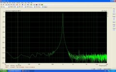
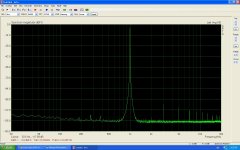
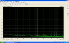
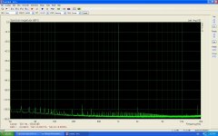
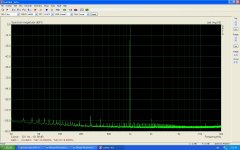
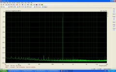
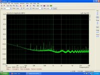
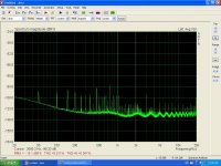
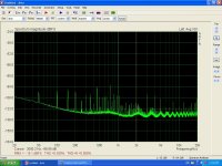
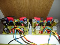
Now i have test another Sound Blaster and then i have done real measurements on VSSA the PMI ver.
Each channel was tested separately .Rload =7R
Amplifier Power supply +/-35v
Vout =4v rms on the Rload(7R)
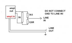
div.3K3+120R parallel to R load.
First picture loop
Second picture Left channel
Third picture Right channel
graph with test configuration
Each channel was tested separately .Rload =7R
Amplifier Power supply +/-35v
Vout =4v rms on the Rload(7R)
div.3K3+120R parallel to R load.
First picture loop
Second picture Left channel
Third picture Right channel
graph with test configuration
Attachments
Last edited:
- Status
- This old topic is closed. If you want to reopen this topic, contact a moderator using the "Report Post" button.
- Home
- Design & Build
- Equipment & Tools
- Issues using E-MU 0404 USB for measurements (ARTA and RMAA)