
That illustrates the screwball mechanicals you need to deal with. The transistor fixture that came with mine looked to have reclaimed edge connector for the connections. The right angle is a B***h to deal with when prototyping.
I have expresspcb layouts for the different fixtures for the 2173 IC box. Never got the boards build. The box is in my storage, and one of its PCB's is at John Curl's. I also have a Zener tester, the 316C resistor analyzer, two noise generators, another transistor tester etc. We should talk. It seems we both need a 12 step program for Quan-Tech. . .
I have expresspcb layouts for the different fixtures for the 2173 IC box. Never got the boards build. The box is in my storage, and one of its PCB's is at John Curl's. I also have a Zener tester, the 316C resistor analyzer, two noise generators, another transistor tester etc. We should talk. It seems we both need a 12 step program for Quan-Tech. . .
I have expresspcb layouts for the different fixtures for the 2173 IC box. Never got the boards build. The box is in my storage, and one of its PCB's is at John Curl's. I also have a Zener tester, the 316C resistor analyzer, two noise generators, another transistor tester etc. We should talk. It seems we both need a 12 step program for Quan-Tech. . .
Demian -- if you send me a PDF/JPEG or CAD files I will have boards burned on the panelization of my next project.
I was fortunate to buy 2 test fixtures from a company in Michigan which was "de-accessioning" their 5173. Have never used the IC fixture.
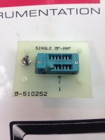
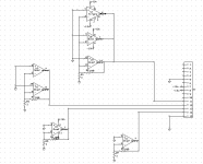
Here is the PCB and schematic in expresspcb format. Its for the older analyzer which only understands single opamps. I reverse engineered the module from John Curl's analyzer to get the dimensions. The original was a single sided PCB. I added a ground plane.
Attachments
One 5173 was showing a moving and increasing noise level in the 10 and 100Hz bands. Alan Stansbury said that when the instruments would come in for repair or Caibration, He wouldn't bother doing anything until a "Capectomy" was performed because nearly all problems with these machines could be traced to gradual increase in ESR of the electrolytic caps. I took a guess that the Electrolytics that would have the greatest effect on Low bands would be the eight 2200uF caps arranged in series-parallel at the base/gate connection prior to the Rs switch (C2401-C2408). replacing these with very low ESR Gold Band Caps brought back the accuracy of the Low band readouts and now no drift after 5 days of being on. Barring very bad semiconducting part failures, He said that the majority of all Cal and poor operation was always due to the Electrolytic capacitor aging which was inevitable in all of the QT instruments. The one thing I added was a pair of silicon diodes nose to nose across the capacitor series and a pair of 3.3 meg resistors in shunt respectively. this balances the leakage and prevents too much potential reverse biasing of these capacitors which can accelerate aging.
Last edited:
The 5173 should be a much easier undertaking than the older box (2173) since it has far fewer boards. A good question would be whether new "solid" caps would work in it. They claim longer life. At least use the high temp caps.
My 315C had a problem with a reed relay. I don't have documentation for it so fixing it was more of a challenge.
When I get my 5173 back (a major High End player is using it for production right now) I'll check the caps in it. Does anyone have a 5173 they want to sell?
My 315C had a problem with a reed relay. I don't have documentation for it so fixing it was more of a challenge.
When I get my 5173 back (a major High End player is using it for production right now) I'll check the caps in it. Does anyone have a 5173 they want to sell?
The total capacitance at the Gate/Base input is an equivalent to a "4500-5000 uF non polar" cap at 16 volts; doing it with solids would be great if you could make up that much C and I would like to see the LF hysteresis for an assembly like that. however cost wise, the gold band Electrolytics at least work far better than the original caps
Searching for 1 - 2 units Quan Tech 5173.
I'm wondering if anyone within earshot has available a working or barely working Quan Tech 5173 for sale, between 1 & 2 units. We had purchased a unit online thru EBay but unfortunately, the wrong model was shipped ( not advertised correctly ). We had committed to sell a unit to an end user overseas. Before shipping the noise analyzer, we have it sent to a test lab for NIST calibration & possible repair if needed. Please advise with details. Email: actronelec@gmail.com ATT: Sid
I'm wondering if anyone within earshot has available a working or barely working Quan Tech 5173 for sale, between 1 & 2 units. We had purchased a unit online thru EBay but unfortunately, the wrong model was shipped ( not advertised correctly ). We had committed to sell a unit to an end user overseas. Before shipping the noise analyzer, we have it sent to a test lab for NIST calibration & possible repair if needed. Please advise with details. Email: actronelec@gmail.com ATT: Sid
Quan-Tech 5173 Mfg Manual
I need a copy of a instruction or tech manual for the Quan-Tech 5173. It would be great if someone had a copy in the .pdf format, but I'm the calibration manager and need a copy in order to qualify the instrument for use. Also, does anyone know of a site that has other mfg manuals in the .pdf format? Thx
I need a copy of a instruction or tech manual for the Quan-Tech 5173. It would be great if someone had a copy in the .pdf format, but I'm the calibration manager and need a copy in order to qualify the instrument for use. Also, does anyone know of a site that has other mfg manuals in the .pdf format? Thx
It's helpful to have a JFET to use as a standard for calibrating the 5173. Quan-Tech used to supply an N-Channel JFET with 1kHz noise of 1nV/Rt Hz. One would measure the noise of the JFET with Rg grounded, and with Rg=10K. The noise in the 1KHz channel would thus register the RMS'd value of the two measurements. If the values didn't compute (~12.8nV/RtHz), there is a potentiometer to adjust.
The problem for most folks is to differentiate between a 1nV/Rt Hz JFET and a 4 or 10nV/Rt Hz device.
It's actually easy enough to do with a measurement amplifier like Denis Colin's which uses a pair of JFET's in parallel to achieve noise better than 1nV/Rt Hz JFET with gain of 100. (Lots of other options such as Scott's LN amp with gain of 1,000). Baseline your instrument with a shorting bar across the input, then measure En of a gained-up JFET with RG=0. You can also measure 10K and 1K resistors on their own to get you in the ballpark.
This even works with a legacy instrument like the HP3581 which has a highest sensitivity range of 100nV and adjustable crystal filter bandwidths. I love my HP3581.
Last edited:
It's helpful to have a JFET to use as a standard for calibrating the 5173. Quan-Tech used to supply an N-Channel JFET with 1kHz noise of 1nV/Rt Hz. One would measure the noise of the JFET with Rg grounded, and with Rg=10K. The noise in the 1KHz channel would thus register the RMS'd value of the two measurements. If the values didn't compute (~12.8nV/RtHz), there is a potentiometer to adjust.
The problem for most folks is to differentiate between a 1nV/Rt Hz JFET and a 4 or 10nV/Rt Hz device.
To the extent I understand your description the 10k resistor is the actual standard, not the JFET. Simply use a BF862--any non-defective specimen will be close enough to 1 nV/rtHz @ 1 kHz without verification.
Samuel
The manual is very specific about the cal process. The FET is part of the amp chain and there is an AGC setup to correct the overall gain to the target value. The FET needs to be low enough noise that the noise of the resistor at the input is being measured. He even includes the drill for correcting out the noise of the fet to confirm the actual noise of the resistor for calibration.
The noise of the stage after the device doesn't need to be that low since the gain of the first stage (the device) should move the noise past any limitations.
The noise of the stage after the device doesn't need to be that low since the gain of the first stage (the device) should move the noise past any limitations.
- Home
- Design & Build
- Equipment & Tools
- Quan-Tech 5173 Advice?