Outstanding blog post, Matt! So very helpful.
Nice article! Does the distortion rise significantly with the 10k source impedance compared to OPA1612?
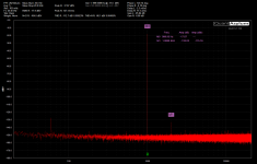
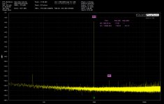
I had to measure to be certain about THD, but the answer is "not much" for THD. Degradation is about under a dB for THD. THDN is about 1.7 dB for 2156 and 5 dB for 1612.
In the plots, you can see the output is -17 dBV, and the measured in is -17.86, which is the 10K source forming a divider with the 100K input.
As an aside, on the QA website Demian correctly observed the hash seemed a bit worse with the 2156. That seems true to me too. When using an external 10K at the end of a BNC cable more stuff seems to be picked up by the cmos versus bipolar. But this is sample size of 1, room temp, nominal voltage etc, so I don't know what to make of it at this point.
Attachments
Thank you for writing it.
The learning is always fun for me and I'm glad it is useful to folks! Do you think the OPA2156 could get a SON package option in the next year?
To reduce noise pickup, the 10K in series with input MUST be placed at the input and not remote at a cable/probe tip.I had to measure to be certain about THD, but the answer is "not much" for THD. Degradation is about under a dB for THD. THDN is about 1.7 dB for 2156 and 5 dB for 1612.
In the plots, you can see the output is -17 dBV, and the measured in is -17.86, which is the 10K source forming a divider with the 100K input.
As an aside, on the QA website Demian correctly observed the hash seemed a bit worse with the 2156. That seems true to me too. When using an external 10K at the end of a BNC cable more stuff seems to be picked up by the cmos versus bipolar. But this is sample size of 1, room temp, nominal voltage etc, so I don't know what to make of it at this point.
At a distance from input, the cable line Z is increased to 10k making EMI/RFI pickup a certainty.
I am wondering about changing one input to OPA2156 cmos. That way, I can choose which QA401 input to use for optimum app. Comment?
THx-RNMarsh
Last edited:
The learning is always fun for me and I'm glad it is useful to folks! Do you think the OPA2156 could get a SON package option in the next year?
Should be on the market around June
")
Should be on the market around June
Thanks, John, the investments you folks are making in audio continues to impress.
That way, I can choose which QA401 input to use for optimum app. Comment?
Definitely doable by a DIYer. The SOIC package is easy to swap back and forth many times if you are careful.
Release 1.709 was released yesterday, and it has a new plug-in for quickly generating graphs of gain and distortion versus input level. This plug-in is mostly useful for folks that are working on musical effects. It is interesting to see how a guitar distortion pedal introduces 2H and 3H distortion based on amplitude of input.
Quantifying Fuzz
-Matt
– QuantAsylum
Quantifying Fuzz
-Matt
– QuantAsylum
Another awesome blog post, Matt!
This blog post went up earlier this week. It covers release 1.71 which has two new plug-ins for DAC evaluation and you can see how quickly a DAC can be evaluated in the link below. The entire plug-in and graphing portion is getting redone in the near future, and it will be much easier to save and compare traces from the sweeps, stack them, do statistical analysis on them, etc.
Rapid USB DAC Evaluation – QuantAsylum
Thanks, Matt
PS. Unless you are really wanting to do DAC evaluation immediately, I'd hold off on the release and wait until the graphing changes are done.
Rapid USB DAC Evaluation – QuantAsylum
Thanks, Matt
PS. Unless you are really wanting to do DAC evaluation immediately, I'd hold off on the release and wait until the graphing changes are done.
Thanks RNMarsh, yes agree there's a lot of value in these types of plug-ins. The next release of the QA401 software posted last night on github, and it is almost a complete re-write of the graphing and plug-in subsystem. From a code standpoint, it's greatly unified and there's a lot more code shared across the different plug-ins. After a bit more cleanup we'll publish the plug-in sources. The hardest thing to wrestle with thus far is the creeping needs for graphing flexibility, and I think we're off in a good direction on the latest release. It's far from perfect, but the foundation is there.
Here's a link to a new video showing how these plug-ins can be used to stack traces and let you see tone knob versus gain changes (for example) overlaid atop each other. The new plug-in design should make this type of task even easier.
Fast Amp Characterization
-Matt
Here's a link to a new video showing how these plug-ins can be used to stack traces and let you see tone knob versus gain changes (for example) overlaid atop each other. The new plug-in design should make this type of task even easier.
Fast Amp Characterization
-Matt
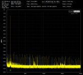
Attached are selftest plots of my QA401. First with a generic USB cable and then with a slightly better USB cable. Normally I would expect dropped frames or other ugly with a bad cable but NOT a major difference in the distortion pattern.
If you get bad results it may be the cable. ijn this case since nothing else was attached I could see no other possible issues and I was first worried that my QA401 had failed somehow. . . but just a funky cable. FWIW the cable shield measures about 500 milliOhms, a decent cable should be closer to 100 milliOhms.
I need to check the voltage at the QA401 end of the cable.
Attachments
Now that is interesting. I was at a presentation last week given by a manufacturer of music servers (Antipodes Audio). The owner and product designer was delivering the talk. He was very focused on getting very low noise transfer of digital signals and was able to demonstrate quite clearly sonic changes with different cables, including Ethernet and USB between server and renderer and renderer and DAC. Your results here may be relevant.
His previous working life was in data transmission in a telecommunications environment.
His previous working life was in data transmission in a telecommunications environment.
I don't think the shield resistance affects the powering. The VBus and Ground are separate wires within the cable.IIUC the USB cable serves as power supply as well. 0.5Ohm resistance at the 500mA specified power consumption = 250mV at 5V - that is not a negligible voltage drop.
USB - Wikipedia
Crummy shield connections can certainly cause other problems. For whatever it's worth, I've been using a USB cable with my QA401 that is higher quality than the usual junk and haven't seen this problem. Lucky, I guess.
Attached are selftest plots of my QA401. First with a generic USB cable and then with a slightly better USB cable. Normally I would expect dropped frames or other ugly with a bad cable but NOT a major difference in the distortion pattern.
If you get bad results it may be the cable. ijn this case since nothing else was attached I could see no other possible issues and I was first worried that my QA401 had failed somehow. . . but just a funky cable. FWIW the cable shield measures about 500 milliOhms, a decent cable should be closer to 100 milliOhms.
I need to check the voltage at the QA401 end of the cable.
Hi Demien, there's a write-up located here on USB noise. The distortions you see looks like a 250 Hz picket fence. That might be the USB polling rate on your machine?
Some particulars that might help with your exploration...
A QA401 draws about 530 mA while running with the attenuator off, and about 480 mA with the attenuator on. That is slightly higher than the USB spec, and in some modes, it can go a bit higher still depending on how fast you can measure.
On a "fat" USB cable (about 4.8mm diameter), they have probably used 22 awg power lines. On a "skinny" USB cable (about 3.5mm diameter) they are probably using 26 or even 28 awg power lines).
On a fat USB cable, you'll see about 90 mV of drop across the cable. That is, with 5V at the head end of the cable, inside the QA401 at 530 mA of load you'll measure around 4.91V. When the USB voltage measures 4.55V inside the QA401 the first regulator to drop out will be the 5V isolated supply. This means at teh head end of the cable, the USB voltage would be around 4.64V, which is about 100 mV below the USB limit.
So, the summary is that if you are using a USB cable with 22g power conductors you shouldn't be facing problems related to voltage sags, drop outs, etc.
Now, back to the picket fence...it's likely not data errors that are giving the picket fence, it's more likely USB supply voltage noise, potentially made worse by a skinny USB cable or a cable where the power lines have been compromised (eg some strands have broken due to repeated flexing and the resistance has creeped up).
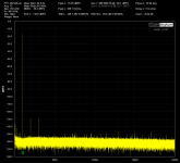
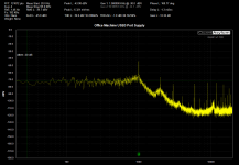
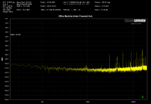
Also, there are some USB ports that are absolutely nasty in terms of the power supplied. In the attached, you can see the USB3 port on the Asus motherboard in my office is 60 dB worse than the Anker powered hub at 1 KHz. This measurement was done by shorting the L- input on the QA401, attaching a scope probe to the L+, and then touching the scope probe with ground lead to the USB supply lines on a breakout board. The breakout board allows the use of data lines but lets you supply power from some other source.
Notice too how pronounced the 1 KHz is on the office machine. That is very likely the USB polling rate on this particular hub.
Do you have a powered hub you could try if the cable swap doesn't solve it?
Attachments
- Home
- Design & Build
- Equipment & Tools
- QuantAsylum QA400 and QA401