Has anyone built a speaker test jig that is balanced? I am a bit greedy in wanting to push my noise floor down. 60 Hz and harmonics, as well as the not-quite-noise free instrument inputs when driven single ended in my 2i2.
Thinking this out-loud here, I float chassis from signal ground in my test gig, then float signal from chassis in my power amp, and add a transformer input to the amp. Anyone been down this path?
Thinking this out-loud here, I float chassis from signal ground in my test gig, then float signal from chassis in my power amp, and add a transformer input to the amp. Anyone been down this path?
I would be inclined to reduce the overall number of black boxes and interconnects. I wouldn't use transformer coupling, for good LF response.
I'm working on a speaker tester with an integrated power amplifier, all single-ended though.
How I would envision a balanced speaker tester:
Voltage divider consisting of R+DUT+R.
Like this, there's no need to mess around with active circuitry just to create a balanced outputs.
Connect one input pair across the DUT, and the other input pair across the entire R+DUT+R divider.
I am getting somewhere passively. The issue is the power amp output is at chassis ground. I had made the old stupid mistake of connecting 2 to 1 on the wrong end of the cable. By lifting the jig chassis bu 1K, I got the signal ground and chassis a little separated, so I got about 6 dB out of those. If I put balanced input receivers in the test amp, that will allow further chassis from signal ground. I am really looking to get actual balanced inputs as in signals 180 out of phase. That takes either electronics or a transformer.
I was not at all worried about LF rolloff or even phase. I am not one of those who believe I need 10Hz for anything. I am not into bragging about frequency response only elephants can hear. 30 is fine for measurements. A transformer is more than sufficient to verify box alignment and to verify crossover design.
So, I am looking for cheap clones of the good Jensen transformers. What do the cheap boxes like Behringer use?
When you get your integrated unit built, please post it. That is a much better idea. I was thinking about tossing a chip-amp into the box. We only need 5W or so clean. Having power there to start with , adding the THAT chips is easy. I may work this up myself. I would love to battery power it, but that is probably not practical.
I don't know what kind of speakers you want to build, but lets say I want to measure the impedance of a woofer with an Fs of 30 Hz, I'll probably want a decade below that of good data. Vented box port frequencies can be in that range too. Like with THD measurements, the measurement system has to be more capable than the stuff you plan to make with it.
If you plan on going below 20 Hz (or wherever there's a certain acceptable THD @ X frequency and Y voltage), then be sure to keep the Volts/Hertz constant. When transformers roll off, they don't roll off smoothly; they add harmonic distortion.
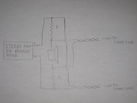
A setup like the following (see pic) will give real differential pairs that your soundcard can record from, with no common-mode voltage I wouldn't expect a non-transformer soundcard to handle. The only thing is you need well matched resistors. This is just for the impedance measurement aspect; everything depends on the functions you want your gadget to do, which are unclear so far.
You can even do the bridged thing using a regular stereo amplifier and a transformer with dual secondaries.
If you plan on going below 20 Hz (or wherever there's a certain acceptable THD @ X frequency and Y voltage), then be sure to keep the Volts/Hertz constant. When transformers roll off, they don't roll off smoothly; they add harmonic distortion.
A setup like the following (see pic) will give real differential pairs that your soundcard can record from, with no common-mode voltage I wouldn't expect a non-transformer soundcard to handle. The only thing is you need well matched resistors. This is just for the impedance measurement aspect; everything depends on the functions you want your gadget to do, which are unclear so far.
You can even do the bridged thing using a regular stereo amplifier and a transformer with dual secondaries.
Attachments
Last edited:
I do my impedance measurements and TSP determination for box design with WooferTester-II, so low frequency is not a problem. Sound Easy would compensate for that somewhat as it compares reference to DUT.
My "sound card" is a Focusrite 2i2. Balanced in and out. It has not given me the troubles my emu-1616m or M-Audio Profire did. It is not transformer input, or I suspect even THAT at it's price. For sure I am never going to see 120 dB CMRR, but 70 would be nice. Enough to get the 120, 180, 240 Hz low enough not to mess up designing BSC or an LT. I am guessing I am about 60 dB now. Workable, but I'm greedy.
I do the complete in-box measurement process with either SoundEasy, ( if I ever get to work all the way through) or LIMP/HOLM adding PSD-lite instead of guessing to do the curve matching. So the bottom end is not important. This is for crossover design. For in room bass tuning, I still fall back to TrueRTA quick sweep mode which is only a mic input.
My current test amp is not bridgeable, but I may have one in the shed that is. That does solve the problem of getting a true floating differential signal.
I don't get what you mean about bridging an amp with dual secondaries. I thought all you needed was a phase splitter on the input, half the gain, re-compensate, and be sure the feedback does not go wild.
- Status
- This old topic is closed. If you want to reopen this topic, contact a moderator using the "Report Post" button.
- Home
- Design & Build
- Equipment & Tools
- Balanced input test jig for speaker testing