Some time ago I started to design a uP-based tube tracer, but, as normal, ran out of time - then in the middle of last year I found that Ronald Dekker, a Professor at TU/e & Philips Research was designing one. Ronald's site is at Ronald's electronic project site.
His device is called the uTracer - the project page is at The uTracer, a miniature Tube Curve Tracer / Tester.. This is a full-featured tester with a Windows-based front-end - the specifications can be found at uTracer specifications.
To cut a long story short, I bought myself the kit as a "me" Christmas present - took a day to build and test. The kit is of excellent quality - the design is very sound - e.g. short circuit & overload protected etc. - you would hope this was the case given the author's profession! The component quality was also very good and the supporting documentation very clear. Layout is good and the build process modular with continual testing. Its very professional.
Now been playing with the results for a few hours - very pleased indeed. All the PSUs (heater, anode & screen) are well-designed SMPS supplies and run cool - I've had the board running non-stop for several hours and it just gets slightly warm.
Whilst the electronics design is "open", the s/w is not - However, Ronald publishes the communications protocol between the PC app and the board should you want to write your own GUI. His rationale for not releasing the s/w source is that he doesn't want it to be ripped off by others - a fair comment in my book, especially when you consider the extraordinary amount of work he's put into designing this, and, for the benefit of all, fully documenting the process and design rationales in his blog - a really interesting read...
All running happily. Examples below of two plots - just playing to learn how to run different classes of tubes... to start with I chose a typical audio triode and pentode.
The attached photos show:
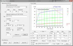
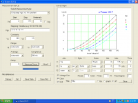
- Setup screen for the 6CA7 tetrode test
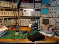
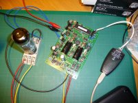
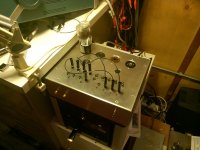
- On the test bench being intimidated:
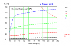
- Electro-Harmonix 6CA7 - Supressor connected to Cathode, 200V on screen, Grid stepped, Va varied and Ia plotted. 25W SOA is also shown. You can clearly see the "tetrode kink" on the graph
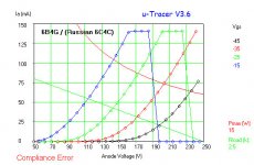
- Svetlana 6C4C (aka 6B4G) - Here, I've overdriven a Russian 6C4C to check that the Iamax limit works (when I hit it the uTester give a "compliance error"). This graph has a 15W SOA curve and a 2.5K Ra load-line as well...
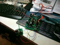
- Completed controller board
Attachments
Last edited:
Here's mine. The kit went together without a hitch, the only hitch was when I ruined the top chassis plate by overzealous milling of the back surface of the top. Long story I don't want to relate, suffice it to say JB Weld works wonders but is ugly. This is a piece of test equipment so I will not be making it prettier.
Note that certain tubes with low voltage filaments need a little finagling to get the filament voltages right.
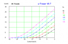
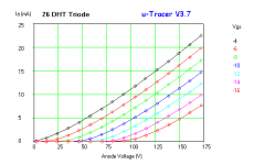
I found using my Keithley 2002 lab DVM that a setting of 2.8 - 2.9V delivered around 1.5 - 1.6V at the tube sockets with a 26 installed. (1.05A filament current)
For the 27 a setting of 3.7V was necessary to achieve 2.5V at the socket. (1.75A filament current) Note that technically the 27 filament current exceeds Ronald's current rating of 1.5A for the filament supply, but I've had no problems. I've fused the filament circuit at 2A.
Tubes with higher voltage, and/or lower current filaments will not have this issue. An external filament supply can always be used.
The voltage setting in the interface panel corresponds to a theoretical PWM duty cycle which when integrated in the filament corresponds to the value set, however the PWM based filament supply operates open loop so various losses conspire to require a higher than expected duty cycle at high load currents and low voltages. (The losses are due to finite on resistance in the mosfet, IR losses in the inductor, and attenuation of the pulses by the ferrites.)
Note on the Keithley 2002 and why direct measurements with many DVM may not work.. This meter has a true rms converter that is flat out to beyond 2.2MHz and can be AC coupled as well, most meters would probably struggle with the 19.5kHz square wave PWM waveform.
Note that certain tubes with low voltage filaments need a little finagling to get the filament voltages right.
I found using my Keithley 2002 lab DVM that a setting of 2.8 - 2.9V delivered around 1.5 - 1.6V at the tube sockets with a 26 installed. (1.05A filament current)
For the 27 a setting of 3.7V was necessary to achieve 2.5V at the socket. (1.75A filament current) Note that technically the 27 filament current exceeds Ronald's current rating of 1.5A for the filament supply, but I've had no problems. I've fused the filament circuit at 2A.
Tubes with higher voltage, and/or lower current filaments will not have this issue. An external filament supply can always be used.
The voltage setting in the interface panel corresponds to a theoretical PWM duty cycle which when integrated in the filament corresponds to the value set, however the PWM based filament supply operates open loop so various losses conspire to require a higher than expected duty cycle at high load currents and low voltages. (The losses are due to finite on resistance in the mosfet, IR losses in the inductor, and attenuation of the pulses by the ferrites.)
Note on the Keithley 2002 and why direct measurements with many DVM may not work.. This meter has a true rms converter that is flat out to beyond 2.2MHz and can be AC coupled as well, most meters would probably struggle with the 19.5kHz square wave PWM waveform.
Attachments
Nice!! Which file format options are available for storage of the measured data?
I've been wanting to build a tube tracer for a while, but have restricted myself from starting more projects until I've finished some of those I have going already. Assembling a board and having the software available would suit me just fine...")
~Tom
I've been wanting to build a tube tracer for a while, but have restricted myself from starting more projects until I've finished some of those I have going already. Assembling a board and having the software available would suit me just fine...
~Tom
interesting board. any chance of interfacing it with something that when combined with this board would provide transconductance and amplification factor. As an example, one manufacters 6550 tube data shows 225V plate voltage, -14v Bias voltage and 12kGm. so we stick the tube in one of our gizomo's and while numbers can scroll in a predictable manner (i.e. as neg bias voltage decreases, bias current increases), we never can seem to be able to reproduce any manufacturers publish tube data in the area of Gm and amplification factor.
Still learning what this thing can do, along with its various quirks. The GUI is coded in VB6 so for plots bmp is the only option, and data is saved in a format that is native to VB6, although I would need to check and see what it is. The program will calculate transconductance but I need to study the blog a bit more to figure out how to get it to do it..
Much more detail here: http://www.dos4ever.com/uTracer3/uTracer3.html
Much more detail here: http://www.dos4ever.com/uTracer3/uTracer3.html
If you are having problems with the inbuilt supply, you are perfectly free to use an external heater source...
The uTracer will plot dIa/dV (first differential of anode current vs. grid voltage for different anode voltages) and the reciprocal of that, i.e. transconductance and gm - you can have two Y axis active at any time.
This video explains how to do it:
uTracer 3, Measuring the Transconductance - YouTube
Note that Ronald has just issued free new FETs to replace the IRF840As in the kit as he's had problems with the recent ones he got from Vishay - the new ones are 07N60C3 - lower Qg & lower RDSon...
Last edited:
...The voltage setting in the interface panel corresponds to a theoretical PWM duty cycle which when integrated in the filament corresponds to the value set, however the PWM based filament supply operates open loop so various losses conspire to require a higher than expected duty cycle at high load currents and low voltages. (The losses are due to finite on resistance in the mosfet, IR losses in the inductor, and attenuation of the pulses by the ferrites.)
I was also interested in the open loop design - Ronald's comments centre around PWM calculations that should deliver the required power to the heater, however, as you correctly state, there are a host of DC losses in the system and no feedback - have you discussed this with him - I've found him very open to comments about the design... it wouldn't be rocket science to check the heater voltage at the heater once the warm-up has completed and to adjust the PWM if needed - you don't need the true RMS value, just the peak voltage at the heater and the delivered pulse width.
Note on the Keithley 2002 and why direct measurements with many DVM may not work.. This meter has a true rms converter that is flat out to beyond 2.2MHz and can be AC coupled as well, most meters would probably struggle with the 19.5kHz square wave PWM waveform.
The reality of "True RMS" DMMs is an interesting one - many so-called true RMS DMMs are always AC coupled and/or ignore any DC component - I use a Tektronix DMM916 which can calculate correct RMS values (including any DC component) but its a grey area that a lot of test kit gets wrong...
Last edited:
I do in fact talk to Ronald regularly, he is extremely knowledgeable and helpful, no one building this kit should be concerned about support - it's excellent. I'm amazed that he and his wife are able to provide all of the coverage they do. The kit is extremely well organized, and carefully packed, reminds me of the good old days of Heathkit.
The filament issue has been discussed and I will simply fine tune the filament voltage settings as required for the tube type I am going to measure. The system is very repeatable so I would not expect to need to make significant adjustments for any given type, but of course the measurements should be performed for any type that uses non-standard filament voltages, and I would recommend having a look if you are running tubes with high filament currents at any voltage. I'd like to avoid using an external filament supply in so far as that is possible.
Quite true that a true rms meter is not required for setting filament voltages accurately, I'm just lucky to have one that gives me accurate enough results. You can measure the peak amplitude value and pulse width vs period, calculate the duty cycle and multiply by the amplitude value to get the effective filament voltage across the tube.
The Keithley 2002 is a rather unusual meter which a former employer used as one of several choices for an internal calibration standard in a small semiconductor ATE test system. It is infinitely configurable and can do simultaneous AC and DC measurements and report the result in a number of ways. It's also insanely accurate and has a up to 11 digit display capability, it's by far the best and most expensive piece of test equipment I own.. (It's not been calibrated since I acquired it so its ultimate accuracy is currently unknown..)
I'm very pleased with my uTracer, not withstanding my chassis mishap, and heartily recommend it to anyone who wants to evaluate specific tube types for appropriateness for a given task. The curves tell a very easily understood story about the merit of any given type.
Repeatability incidentally is excellent. I've measured the same tube over a number of times and compared the results, they match extremely closely day to day. (I can't see any discernible differences in the curves I've taken.)
It occurs that this could be easily adjusted for in firmware as part of the calibration setup for the uTracer - The static DC losses could easily be adjusted for - Ronald makes absolute assumptions in his PWM calculation which excludes these losses - a simple setup check with a load resistor (low ohms, decent wattage) and a diode + capacitor to catch the peak (say an 1N4148 with known Vf) would probably work.
Alternatively, and much simpler, is a simple h/w mod to use one of the uP ADCs to measure the heater output during the PWM pulse and adjust the pulse width accordingly - that would automatically compensate for any losses in the system...
I might suggest that to Ronald !
Alternatively, and much simpler, is a simple h/w mod to use one of the uP ADCs to measure the heater output during the PWM pulse and adjust the pulse width accordingly - that would automatically compensate for any losses in the system...
I might suggest that to Ronald !
Hello guys,
I have the kit from Ronald too and I am a very happy new user
Just for fun : you can mesure the temperature of a resistor in a not electricaly conducting cooler liquid by mesuring the temperature of the cooler liquid itself, to have a true RMS value. Of course, the difficulty is to calibrate the temperature mesurement tape (by comparing with a good RMS voltmeter in parallel with the load) and to have enougth power to dissipate to heat the cooler liquid.
Some HF power true load have an output to do that, but it's for high power output only. Another little thing to experiment for low power ?
Best Regards,
Francois (France)
I don't think you would attain even moderate accuracy due to losses to the surrounding environment and a very long time constant using the approach you propose..
True RMS converter - Wikipedia, the free encyclopedia Links to thermal converter..
http://en.wikipedia.org/wiki/True_RMS_converter#Thermal_converters
True RMS converter - Wikipedia, the free encyclopedia Links to thermal converter..
http://en.wikipedia.org/wiki/True_RMS_converter#Thermal_converters
I discussed this with Ronald and we agreed that due to inductive and other effects at high current the waveform of the heater pulse is far from rectangular and therefore its not possible to estimate accurately - it would need a true-RMS continuous integration to get an accurate result...
Maybe for V4
Maybe for V4
I don't think you would attain even moderate accuracy due to losses to the surrounding environment and a very long time constant using the approach you propose..
True RMS converter - Wikipedia, the free encyclopedia Links to thermal converter..
http://en.wikipedia.org/wiki/True_RMS_converter#Thermal_converters
Barring an HP3403C or Fluke 8920A, the Linear Tech sigma-delta chips are quite good: http://cds.linear.com/docs/en/application-note/an106f.pdf
Barring an HP3403C or Fluke 8920A, the Linear Tech sigma-delta chips are quite good: http://cds.linear.com/docs/en/application-note/an106f.pdf
AD8436 is a nice chip too:
AD8436 datasheet and product info | Low Cost, Low Power, True RMS-to-DC Converter | RMS to DC Converters | Analog Devices
Tube socket selection
Hello Folks,
My U-Tracer kit should arrive sometime this week.
I am now trying to figure out what selection of tube sockets make the most sense.
For now, I have the following sockets in mind (descriptions based on this site)...
4 pin standard (C4B)
5 pin standard (C5B)
7 pin miniature (C7MA)
8 pin octal (C8CF)
9 pin miniature (C9MA)
Am I missing any important Audio tube sockets?
Depends on whether or not you are interested in Compactron tubes. If so, add the 9 NOVAR and 12 pin compactron sockets.
Thanks Gimp. I will add the following
9 pin Compactron (C9)
12 pin Compactron (C12F)
Hello guys,
Personaly, I have not selected all support to place on only one box/board, but one socket/one board. One is for noval, one for octal, etc...
Each "support box" owns 2mm miniature safe bananas supporting high voltage.
Like this, I can evoluate by creating a new box for each strange, unknown, forgotten valve support when needed without necessitiy to redo a complex wiring head lock, with lot of parasit capacitors, oscillation risks, but only very very shorts standard 2mm safe bananas
Simple is often the best !
Best Regards,
Francois/France
- Home
- Design & Build
- Equipment & Tools
- uTracer...