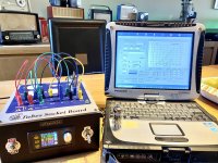
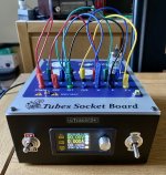
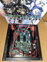
I've had this kit for a few years, every time something else came in the way, but I finally finished it and it is working nicely.
Now I need to go through my roughly 150 "NOS" Telefunken/Mullard/Amperex/RCA tubes and see how many times sellers fooled me.
Quick question, when measuring dual triode simultaneously, my understanding is to use Vs for the second plate, connect the grid to both grids, ... what to connect for the second cathode? Both cathodes in parallel ?
Attachments
What is the preferred approach to matching pentodes and triodes? Should you prioritize Ia at a given operating point or Gm or mu?
Based on my reading, for pentodes better to match on Gm and triodes on mu, but what about the other parameters e.g, if mu is matched, how important is Ia at the given operating point?
Based on my reading, for pentodes better to match on Gm and triodes on mu, but what about the other parameters e.g, if mu is matched, how important is Ia at the given operating point?
a bit late response, but indeed, for dual triodes you have to parallel/duplicate the grid and cathode connections and only Anode and Screen wires should be connected separately to anode1 and anode2.
The matching depends on the final application, you can match on Gm, you can match on DC current in the operational point. In my uTracerJS I even implemented for one of the users a case, where the matching is done on the same current but one finds for which Vg it actually happens. Sometimes when you acquire actual curves, you can even see that the tubes can be called "matched" for some points and not for other, it depends if your future amplifier will work around that point or in a totally different part of the parameter space")
The matching depends on the final application, you can match on Gm, you can match on DC current in the operational point. In my uTracerJS I even implemented for one of the users a case, where the matching is done on the same current but one finds for which Vg it actually happens. Sometimes when you acquire actual curves, you can even see that the tubes can be called "matched" for some points and not for other, it depends if your future amplifier will work around that point or in a totally different part of the parameter space
Hi,RMS to DC converter
I did just that, except the implementation of a control loop. Instead, the output of the RMS to DC converter is readout by an analog panel meter. The AD737 is not really suitable for this task, as the maximum crest factor is only 5:1, while one needs at least 20:1. In this respect the LT1188 is more suitable, as the max. crest factor is 50:1. As far as I know, this is the only chip with such a high permissible crest factor. Regrettably, this beautiful chip is obsolete by now, but you can still buy it on ebay.
One may ask is it worth the time, money and effort to add RMS to DC converter to the uTrace? Yes, it is, as the real filament voltage is some 5% lower than specified in the menu. Especially in case of used tubes, this deviation has a noticeable impact on screen and anode currents.
Below you see the schematic, step responses and PCB. The Zener network at the right mimics a quadratic transfer function to compensate the quadratic voltage-temperature relation of the LT1188 (remember it's the power that defines the temperature). Without this network the step response is much slower (see 3rd pic, hor. scale = 1s/div).
For those who wants to build this converter, I've some spare PCB. You can get them for free, except postage (send me a PM).
Cheers, E.
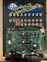
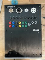
I've build the uTracer3+ ( See pics ) and would be interested in you RMS to DC converter , do you have a spare pcb or gerber files ?
Thank you ,
Danny
Attachments
Hi Danny,Hi,
I've build the uTracer3+ ( See pics ) and would be interested in you RMS to DC converter , do you have a spare pcb or gerber files ?
Thank you ,
Danny
I still have a few PCB's. Send me a pm with your name + address and you will get one.
Cheers, E.
@Edmond Stuart I'm new here and under moderation , can't use PM to communicate ........