I don't have any experience with tubes but have repaired a few tube Guitar amps. I have A tube microphone and a few tube microphone preamps. I have access to a tube tester for a good price. Would it be useful to me for maintence or diagnosis? Does a tube tester only test good or no good? Can a tube tester be used to match tubes or check other variables? This one has an analog meter on it.
Thanks
Thanks
I don't have any experience with tubes but have repaired a few tube Guitar amps. I have A tube microphone and a few tube microphone preamps. I have access to a tube tester for a good price. Would it be useful to me for maintence or diagnosis? Does a tube tester only test good or no good? Can a tube tester be used to match tubes or check other variables? This one has an analog meter on it.
Thanks
Hi,
This is an attempt to make a simple tubetester for the most common E-types as EL84, EL34, KT88, ECC81,82,83 , 12BH7 and 6SN7...and more types later. You can find the test setup at my amateur site:
TUBEAMP ...on the site look for "Tubetester" and datasheet for Telefunken, M-O Valve, GE, Siemens & Halske, Sylvania a.o.
The test setup should be able to tell you whether the tube has gas leak , and whether you have 100% emission. Microphonic tubes can be found by knocking on the glass...you will have a ringing-sound.
regards
Nice one, thanks for that.
")
Nice one, thanks for that.
You're welcome,
As the Gm and Mu is understood:
Someone mentioned Gm for tubes :
Transconductance is termed as the change of the current in amperes of the anode for each volt we change the voltage on the control grid, with all other factors held constant.
In other words...if we have the setup I mentioned from my amateur site with two variable voltages ...one 0-300V for the plate, one neg. 0--120V for the grid, it is possible to draw the Gm lines on a datasheet paper... by change of the negative voltage of -1V step by step. I know it takes some time....
Mu = gain
The gain in Mu, describes an voltage change in volts at the anode for each volt we change the voltage on the control grid, with all other factors held constant.
In other words:
If we take the 250V dc as reference on the plates and starts with the -7,3V on the grid of a EL84 ...and then we reduce from the - 7,3V with 0,1V / 1/2V step (up and down) it is possible to read and write the platevoltage down on the datasheet....I know it takes some time...
Just a proposal....
regards
Hi,
you write:
"The gain in Mu, describes an voltage change in volts at the anode for each volt we change the voltage on the control grid, with all other factors held constant."
Wich is perfectly true and means the the anode current MUST be held constant.
But the anode current will change when changing grid voltage (as for Gm measurement), so you must readjust the plate supply voltage to restore the same plate current.
It is the value of this "readjustment" wich is the Mu.
Another way is to measure the Rp (wich is Mu / Gm).
This can be done by changing the plate voltage with all other factors held constant while plotting the coresponding current change and you know Rp as dVP / dIP.
Since Gm is already know, you can compute Mu as Rp * Gm.
Because Gm is usually expressed in µmho, Rp must be expressed in Mohm.
Yves.
You're welcome,
As the Gm and Mu is understood:
Someone mentioned Gm for tubes :
Transconductance is termed as the change of the current in amperes of the anode for each volt we change the voltage on the control grid, with all other factors held constant.
In other words...if we have the setup I mentioned from my amateur site with two variable voltages ...one 0-300V for the plate, one neg. 0--120V for the grid, it is possible to draw the Gm lines on a datasheet paper... by change of the negative voltage of -1V step by step. I know it takes some time....
Mu = gain
The gain in Mu, describes an voltage change in volts at the anode for each volt we change the voltage on the control grid, with all other factors held constant.
In other words:
If we take the 250V dc as reference on the plates and starts with the -7,3V on the grid of a EL84 ...and then we reduce from the - 7,3V with 0,1V / 1/2V step (up and down) it is possible to read and write the platevoltage down on the datasheet....I know it takes some time...
Just a proposal....
regards
Why bother, I use a XY writer for that, and a 0-300v power supply
set the grid voltage, Pen down sweep anode voltage , Pen up set grid voltage.
it takes about 1 to 2 minutes
cheers, v4lve.
Wonder if you guys have seen this?
The uTracer, a miniature Tube Curve Tracer / Tester.
The uTracer, a miniature Tube Curve Tracer / Tester.
Hi,
Wich is perfectly true and means the the anode current MUST be held constant.
But the anode current will change when changing grid voltage (as for Gm measurement), so you must readjust the plate supply voltage to restore the same plate current.
It is the value of this "readjustment" wich is the Mu.
Yves.
Thank you for your answer Yves.
First thought was a question of "go or no go" tubes, because many of us has used or old tubes in stock. But things do develope and we want more.
I did write about keeping the plate constant, and this should have been current!
Why bother, I use a XY writer for that, and a 0-300v power supply
set the grid voltage, Pen down sweep anode voltage , Pen up set grid voltage.
it takes about 1 to 2 minutes
cheers, v4lve.
But v41ve, "Things comes to those who has patience" ...one step at a time
Happy new year
Wonder if you guys have seen this?
The uTracer, a miniature Tube Curve Tracer / Tester.
It looks like a great tool and a fine measuring instrument for 215 €.
The intention was a very simple test setup for the most common E-tubes for autodidact electronic people like me . A simple test setup which could determine whether a used/old tube had 100% emission.
Another interesting point would be to estimate the remaining life-time of a tube?
Hello,
Here's what I use : Metrix 310CTR, Hickok 600, Knight 600A.
And these ones - when I will them delivered on mid-end January 2013 - after checking, possible maintenance and calibration : Hickok 752A, 539B+CA4.
If I need more precision, I built a bench test with my DIY HV, Bias and Heater variable DC regualted PSUs, Flukes FL87 III & V DMMs, and use an audio signal generator to make dynamic Gm measurements.
I hope that Zibi will give us more information about the fine Polish EPO508 Tube Tester...
A+!
Here's what I use : Metrix 310CTR, Hickok 600, Knight 600A.
An externally hosted image should be here but it was not working when we last tested it.
And these ones - when I will them delivered on mid-end January 2013 - after checking, possible maintenance and calibration : Hickok 752A, 539B+CA4.
An externally hosted image should be here but it was not working when we last tested it.
An externally hosted image should be here but it was not working when we last tested it.
If I need more precision, I built a bench test with my DIY HV, Bias and Heater variable DC regualted PSUs, Flukes FL87 III & V DMMs, and use an audio signal generator to make dynamic Gm measurements.
I hope that Zibi will give us more information about the fine Polish EPO508 Tube Tester...
A+!
Wonder if you guys have seen this?
The uTracer, a miniature Tube Curve Tracer / Tester.
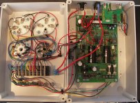
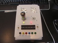
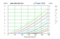
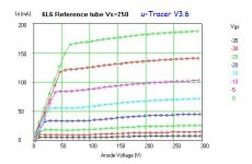
Yes I have one, It is great, you can do some nice measurements
here are some pictures
Attachments
Hello,
Here's what I use : Metrix 310CTR, Hickok 600, Knight 600A.
And these ones - when I will them delivered on mid-end January 2013 - after checking, possible maintenance and calibration : Hickok 752A, 539B+CA4.
If I need more precision, I built a bench test with my DIY HV, Bias and Heater variable DC regualted PSUs, Flukes FL87 III & V DMMs, and use an audio signal generator to make dynamic Gm measurements.
I hope that Zibi will give us more information about the fine Polish EPO508 Tube Tester...
A+!
Chocked!! ...are all those tubetesters yours (collecting)?.....or do you renovate the testers for resale? Don't know Zibi's Polish EPO508 tube tester, or is it "Jacmusic's"?
Yes I have one, It is great, you can do some nice measurements
here are some pictures
Hi,
The test instrument of yours, "The uTracer", really looks fine. Would you mind tell me the build price including the plastic mounting cabinet? Did you receive construction papers together with the "uTraser" PCB?
Regards Kim
Hi,
The test instrument of yours, "The uTracer", really looks fine. Would you mind tell me the build price including the plastic mounting cabinet? Did you receive construction papers together with the "uTraser" PCB?
Regards Kim
Hi Kim,
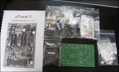
The uTracer is kit, it has the PCB and all components needed to build the PCB, including the construction manual. In the picture you can see what's in the kit
You can download the construction manual at the download section atThe uTracer, a miniature Tube Curve Tracer / Tester.
You can allready see how the PCB is build, and download the software
It uses an old Laptop powerunit to power. So no big expensive transformers needed.
The kit is 195 Euro.
On my tracer I use an USB to TTL convertor for the connection to my PC, My PC has no serial connection. The convertor is a kit from ELV more info here: Optisch getrenntes USB-Modul UO 100, Komplettbausatz | ELV-Elektronik
I use some old Tube sockets, a noval, a octal, an UX4 and an UX5 socket and some wire.
The thumbswitches are expensive and costed around 80 euro, but I connected them the same way as the selector of my AVO MK4 tester. This way I can test every noval and octal socket tube together with the AVO Valve data manual.
The casing is about 10 Euro, it's just a plastic case 20x30X10cm. I also have the ferrite beads on my wires between the sockets.
I think all together I spend 300 - 350 Euro.
For all information and examples of other builders you should look at: The uTracer, a miniature Tube Curve Tracer / Tester.
Attachments
Chocked!! ...are all those tubetesters yours (collecting)?.....or do you renovate the testers for resale?
Hi leakstereo20,
Yes, these instruments are mine, I service them and use them for servicing amps (guitar, bass and audio), troubleshooting problems tied to tubes... And yes, I must confess that I like that kind of instruments too !
Zibi is from Poland, so he may have more info about the Polish EPO508 tube tester. Or maybe he only took the pictures on jacsmusic's website also ?
A+!
I built one of these at the end of last year - just started a thread about it in this forum earlier today - http://www.diyaudio.com/forums/tubes-valves/227013-utracer.htmlWonder if you guys have seen this?
The uTracer, a miniature Tube Curve Tracer / Tester.
Great bit of kit - having enormous fun with it - very well designed and good quality. Easily worth the money. The GUI is a "work-in-progress" but still good and improving all the time. As the h/w is completely controlled by the Windows s/w, functionality will only improve even more.
I have some very nice Hickok testers, including a pristine 539C, and this little beastie wipes the floor with it...
Cheers
Last edited:
Yes I have one, It is great, you can do some nice measurements
here are some pictures
I was chatting to Ronald about your implementation - those thumbwheel switches are normally only rated for 100mA switching and 500mA max @ 250V.
That means you may have a serious risk of a meltdown on the heater switches and and arcing on the screen & anode...
Though the thumbwheels look neat, I've decided to go the simple plug-and-socket route...
- Status
- This old topic is closed. If you want to reopen this topic, contact a moderator using the "Report Post" button.
- Home
- Design & Build
- Equipment & Tools
- Tube tester