Hi,
I hope so to submit to the right discussion.
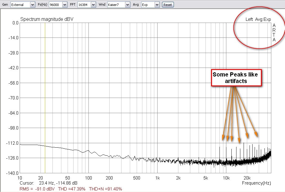
I use the emu like a measurement tool for measure dac's, amps e.t.c
I have a problem with the noise on left channel of my emu 0404.
There are always some "artifacts of peaks" at 8KHz, 10KHz, 12KHz and so on.
The right channel is without problem.
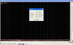
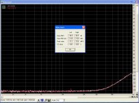
Because my english is not good, I have attached an ARTA noise measuring capture with external loopback (analogue line out -> line in), but the same happens and without any connection, only FFT record of noise.
I have seen the same behaviour and to another used emu 0404 usb at the same left channel with the same peaks!
Any suggestion what is the reason?
I hope so to submit to the right discussion.
I use the emu like a measurement tool for measure dac's, amps e.t.c
I have a problem with the noise on left channel of my emu 0404.
There are always some "artifacts of peaks" at 8KHz, 10KHz, 12KHz and so on.
The right channel is without problem.
Because my english is not good, I have attached an ARTA noise measuring capture with external loopback (analogue line out -> line in), but the same happens and without any connection, only FFT record of noise.
I have seen the same behaviour and to another used emu 0404 usb at the same left channel with the same peaks!
Any suggestion what is the reason?
Attachments
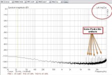

Yes, it works fine with Win7 on my laptop (beta driver for 32bit OS).
I see that there is the same behaviour and yours emu on the left channel.
But why only on the left channel and not to right?
There is must an explanation about this and must be a solution for this. A new one emu has no any problem to the left channel.
It has the same behaviour with all sampling rates, with 16/24bit resolution.
I have changed the last capacitors on the left input but with no success.
It is just a hunch....Since the two audio clocks don't seem to be responsible for those bins (each is turned off when the other is used) there are two suspects left:
1.a USB controller (something with a 12MHz crystal)
2. (less likely) a DC-DC converter used to boost/make a negative rail for the analog supply
One of these is close to the left channel circuits managing to radiate some noise into them.
I always wanted to open it and see exactly what it is used inside, altough I'm pretty sure that everything is crammed on a multilayer board and identifying the cause will be next to impossible....
There's a thread or wiki on this site in which I tried to identify the on-board chips. There were quite a few dc-dc converters to provide various positive and negative rail voltages, all running at various kHz speeds.
Edit: found it. http://www.diyaudio.com/wiki/E-MU_0404_USB_mod_wiki
Edit: found it. http://www.diyaudio.com/wiki/E-MU_0404_USB_mod_wiki
Thanks Ikoflexer,
Starting from that thread I did some homework and found these links of interest:
Inside view
Loopback tests
I also opened my unit and I think I found the problem . They announced some rain in Montreal this week-end... so stay tuned. I will post pictures and a step-by-step "how to"... if my fix works.
There are no door prizes but if anyone cares to take a guess...
Starting from that thread I did some homework and found these links of interest:
Inside view
Loopback tests
I also opened my unit and I think I found the problem
. They announced some rain in Montreal this week-end... so stay tuned. I will post pictures and a step-by-step "how to"... if my fix works.There are no door prizes but if anyone cares to take a guess...
oh I dunno, the 12MHz crystal, plus what appears to be DGND and some DC->DC convertors in the second pic, folds over when closed and sits directly above the dac? in the pic with the boards folded out like a book it appears that section will sit directly above and VERY close
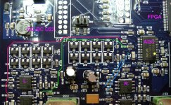
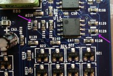
 I have a bunch of photos, starting with a general view of the troubled area. I ruled out the DAC and output circuits since (luckily) these did not meet the conditions.
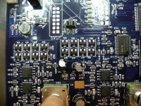
Next one shows a "textbook" example on how a differential pair should not be routed !
The ADC has a yellow dot where the AINL pins are. All is good up to the anti-glitch capacitor C101 which is not far, but after that the show is on...the traces go on different inner layers and cross each other and then come on top at R151 (from pin 4) and R167 (from pin 5).
The colors tell the rest of the story, a nice loop is formed (the green trace even changes layer, where dotted, near the top right sot23s). There is a DC-DC converter right above with an unshielded inductor, L6 and an FPGA that has to run data at USB rates (plenty of traces there parallel to our top trace).
On a brighter note the blue lines show the right channel pair routed on a inner layer and top layer. They're close togheter and far from dangers.
I guess waiting for a board revision is out of the question, since the 0404 is obsoleted
! The ADC has a yellow dot where the AINL pins are. All is good up to the anti-glitch capacitor C101 which is not far, but after that the show is on...the traces go on different inner layers and cross each other and then come on top at R151 (from pin 4) and R167 (from pin 5).
The colors tell the rest of the story, a nice loop is formed (the green trace even changes layer, where dotted, near the top right sot23s). There is a DC-DC converter right above with an unshielded inductor, L6 and an FPGA that has to run data at USB rates (plenty of traces there parallel to our top trace).
On a brighter note the blue lines show the right channel pair routed on a inner layer and top layer. They're close togheter and far from dangers.
I guess waiting for a board revision is out of the question, since the 0404 is obsoleted
Attachments
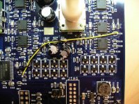
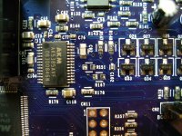
The fix is obvious.
1. Lift R151 and R167
2. Cut the traces near the pads of R123 and R128 as shown, making sure not to go too deep or to chip some neighboring components.
3. Solder a pair of wires, twisted a couple of times, to rework the connection. On the right side I chose the pads of R108 and R110 which belong to the same original nodes while for the left side I used the leftmost pads of R151 and R167. I did not want to pass the wires over the ADC to C101, not optimal in my opinion. Make sure not to reverse the phase.
Note: Photos are now turned upside down, makes easier to read component designators... sorry, my bad.
Attachments
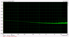
I reassembled my EMU without any other touch-ups or upgrades. Apart from the mod shown my unit is still in "stock" form. As external supply I use a breadboarded LT3080 supplied with a 9V switching walwart.
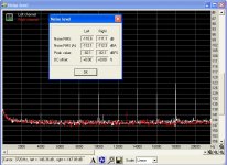
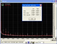
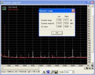
Before showing the results I will post for reference some older tests. The photos are lower rez and cropped differently than the new ones. On top of that I don't recall the sample rates used but by their looks they're higher than 88.2k.
But it doesn't matter anyway - as you'll see later.
The left channel looks pretty busy...
Attachments
- Home
- Design & Build
- Equipment & Tools
- E-MU 0404 USB 2.0 and some "artifacts peaks" on left channel