Happy New Year to everyone!
If you can't find the Alpha 10K main level pot, there is an equivalent from Bourns (PTV112-4420A-B103)
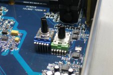
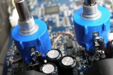
Here side by side by Alpha pot

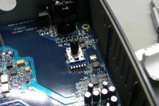
Here it is, after change it.

I would like to change the two inputs of ADC pots with the multiturn precision pots. They seems to be 20K with 4pins legs.

From what I have seen, the four legs from left to right, only the first three are operated, the last one not.
The combination of 1+3 and 2+3 gives the same (almost) result. I don't know well but it is related with xlr input (cold, hot).
I would like to put a multiturn precision Bourns pot (3590S-2-203L) 10 turns, but it has 3 legs.
If I connect the middle leg of precision pot to the 1&2 position of pcb it will be good?
If you can't find the Alpha 10K main level pot, there is an equivalent from Bourns (PTV112-4420A-B103)
Here side by side by Alpha pot
Here it is, after change it.
I would like to change the two inputs of ADC pots with the multiturn precision pots. They seems to be 20K with 4pins legs.
From what I have seen, the four legs from left to right, only the first three are operated, the last one not.
The combination of 1+3 and 2+3 gives the same (almost) result. I don't know well but it is related with xlr input (cold, hot).
I would like to put a multiturn precision Bourns pot (3590S-2-203L) 10 turns, but it has 3 legs.
If I connect the middle leg of precision pot to the 1&2 position of pcb it will be good?
Attachments
Last edited:
I was wrong about ADC input pots.
I removed them and the type is Alpha RV110F4020A02C20K 20K pot but measured about 3 Ohm - 17.6KOhm at the edges.
The pins are typical Pin1....Pin2(variable)....Pin3
Unfortunately the Bourns precision multiturn rise up some spikes of noise, cause the length of cable btw pcb and pot legs. The sense of tuning for exactly level is marvelous!
I am searching for a solution...
The EMU input circuit is differential and the pot functions as a variable resistor between two active nodes. You really only need two connections per channel to the pot but keep in mind that it works in reverse, the smallest resistance will be the highest gain (max clockwise).
One pin will most likely be grounding for the shaft. Its important because noise from either touching the shaft or intermittent connection to the shaft is quite audible.
The Bourns pots for the output are way better both in measured distortion and sonically than Alpha pots. I think that change would be well worth the effort. The wirewound multiturn pots may have higher "noise" when rotating but should be low noise when set. The internal inductance usually won't show in audio applications. The Vishay bulk foil trimmers are the best option if you can figure out how to implement them. http://www.vishaypg.com/docs/63055/Accutrim-1202.pdf There is a clip that will hold them to a panel and provide a thin shaft to pass through a panel. I found it!: Spectrol / Sfernice / Vishay - 6-1-1 - Trimmer Hardware - Mounting Adapter - Allied Electronics
Hello again,
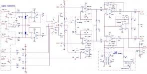
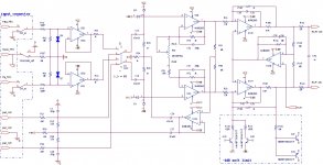
For those still interested I have some interesting schematics. Considering their quality, better never than later...") ! (I wanted to capture the whole screen ignoring that the RefDef's and values might appear too small). Anyway let's start with the inputs.
! (I wanted to capture the whole screen ignoring that the RefDef's and values might appear too small). Anyway let's start with the inputs.
Considering the price point and the functions it has to cover I think that the circuitry is quite well designed. Many of you will recognize Bill Whitlock's patented bootstrapped input (not an expert but I will assume that everything was settled financially/legally – let's hope we're not upsetting anybody).
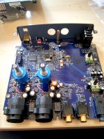
I agree with 1audio that the only worthy mod would be to clone a AK5394 pcb with or without optimized analog circuitry. The third attachment shows what I did to my left channel .
.
About the Pot, I replaced the original anti-log 20k with a 10k linear (P110KH1-0F25BR10K, or 987-1290-ND at Digikey). Now it is easier to adjust and match the channels around “0dB” but not so easy at high gains. I also disabled the +48V dc-dc converter and removed most of the “pleasing -6dB soft limiter”
Personally I don't need the XLR MIC input (low impedance, carries also the phantom power). Only the TRS input is of interest for the type of measurements I'm doing (TS for single ended sources). Also the GND-Lift switch only works for the TRS connection.
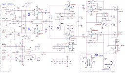
For those interested to perform some of these mods it is very important to use close tolerance parts - I used 0.05% thin film resistors in most places. In red the parts that changed type or value, NI means not installed and you will recognize "our mod" the wire straps over R151, 167.
For those still interested I have some interesting schematics. Considering their quality, better never than later...
! (I wanted to capture the whole screen ignoring that the RefDef's and values might appear too small). Anyway let's start with the inputs. Considering the price point and the functions it has to cover I think that the circuitry is quite well designed. Many of you will recognize Bill Whitlock's patented bootstrapped input (not an expert but I will assume that everything was settled financially/legally – let's hope we're not upsetting anybody).
I agree with 1audio that the only worthy mod would be to clone a AK5394 pcb with or without optimized analog circuitry. The third attachment shows what I did to my left channel
.About the Pot, I replaced the original anti-log 20k with a 10k linear (P110KH1-0F25BR10K, or 987-1290-ND at Digikey). Now it is easier to adjust and match the channels around “0dB” but not so easy at high gains. I also disabled the +48V dc-dc converter and removed most of the “pleasing -6dB soft limiter”
Personally I don't need the XLR MIC input (low impedance, carries also the phantom power). Only the TRS input is of interest for the type of measurements I'm doing (TS for single ended sources). Also the GND-Lift switch only works for the TRS connection.
For those interested to perform some of these mods it is very important to use close tolerance parts - I used 0.05% thin film resistors in most places. In red the parts that changed type or value, NI means not installed and you will recognize "our mod" the wire straps over R151, 167.
Attachments
Last edited:
1audio thanks for the help.
Excelent work sidiy! Many thanks for these circuit captures!
I have the same think, that the best would be to clone a AK5394 pcb with or without optimized analog circuitry.
I need the phantom power for xlr measuring microphone (room estimating).
I don;t know what I do now! I procced with the 20K Bourns precision multi turn that I bought or put the P110KH1-0F25BR10K that sidiy suggest!
Look my installing untill now...
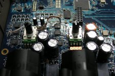
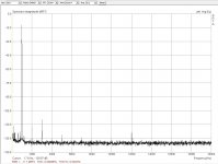
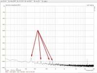
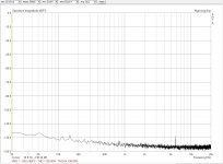
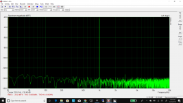
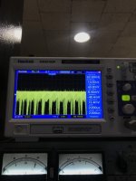
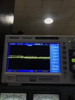
Start I used an utp cable with female pins to join with the pot (10cm approximately) but I had a lot of spikes, the circuit picks some noise (Long cables Left vs Right Ch, attatchment).
Then I used fixed wire from pcb to pot (Multi Turn Bourns1/2/3, attachments).
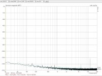
The spikes are less now! (Noise Floor Left multiturn vs Noise Floor Right, attachments).
The thd is fine.
All the measures are loopback.
Excelent work sidiy! Many thanks for these circuit captures!
I have the same think, that the best would be to clone a AK5394 pcb with or without optimized analog circuitry.
I need the phantom power for xlr measuring microphone (room estimating).
I don;t know what I do now! I procced with the 20K Bourns precision multi turn that I bought or put the P110KH1-0F25BR10K that sidiy suggest!
Look my installing untill now...
Start I used an utp cable with female pins to join with the pot (10cm approximately) but I had a lot of spikes, the circuit picks some noise (Long cables Left vs Right Ch, attatchment).
Then I used fixed wire from pcb to pot (Multi Turn Bourns1/2/3, attachments).
The spikes are less now! (Noise Floor Left multiturn vs Noise Floor Right, attachments).
The thd is fine.
All the measures are loopback.
Attachments
-
 Multi Turn Bourns3.jpg142.2 KB · Views: 514
 -
 Multi Turn Bourns2.jpg155.9 KB · Views: 560
 -
 Multi Turn Bourns1.jpg256.6 KB · Views: 597
 -
 thd_48KHz loopback left ch.jpg103.4 KB · Views: 502
 -
 Noise Floor Left (multiturn).jpg122.2 KB · Views: 439
 -
 Noise Floor Right.jpg107.7 KB · Views: 432
 -
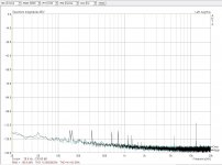 Long cables Left vs Right Ch..jpg118.3 KB · Views: 784
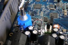
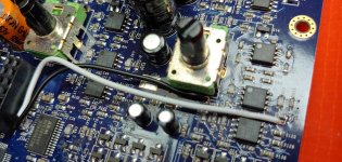
I think that I have a good result now...
I changed all the connecting wires from the pcb to pot and make the connection with the ferrites (see the attachment photo).
I was doing this to the two channels.
I think that the Noise Floor is good now and the spikes has 98% gone!
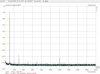
Here again a loopback thd and noise floor measures, both channels.
I changed all the connecting wires from the pcb to pot and make the connection with the ferrites (see the attachment photo).
I was doing this to the two channels.
I think that the Noise Floor is good now and the spikes has 98% gone!
Here again a loopback thd and noise floor measures, both channels.
Attachments
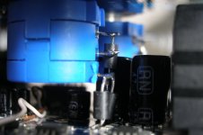
Did the Bourns multi-turn pot mod as well some time ago; the wire bypasses as well. No more cursing on those darn gain controls 
Tight fit though; but works out fine
Tight fit though; but works out fine
Attachments
I proceed to change all the stock left input opa's and the output opa's of EMU with the LME49720.
My purpose was the THD improvement.
There is any significant improvement to THD, except the D2 measuring at the step test.
For full information about this see at http://www.diyaudio.com/forums/equi...sound-card-audio-analysis-14.html#post4412914
My purpose was the THD improvement.
There is any significant improvement to THD, except the D2 measuring at the step test.
For full information about this see at http://www.diyaudio.com/forums/equi...sound-card-audio-analysis-14.html#post4412914
Hi all,
In trying to implement Sidiy's mod, I lost the left pad of R151. Any known cure?
I'm learning SMD work and I guess first lesson didn't go too well.
Thank you!
On an alternate plan, is anyone having done the modification willing to sell their modified EMU 0404? I think I had enough SMD teachings for a while.
Last edited:
Hi all,
In trying to implement Sidiy's mod, I lost the left pad of R151. Any known cure?
I'm learning SMD work and I guess first lesson didn't go too well.
Thank you!
On an alternate plan, is anyone having done the modification willing to sell their modified EMU 0404? I think I had enough SMD teachings for a while.
Connect to C101, obviously. Any thoughts on optimal size of wire? I'm traumatized after exfoliating the R151 pad.
Connect to C101, obviously. Any thoughts on optimal size of wire? I'm traumatized after exfoliating the R151 pad.
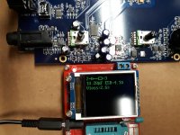
Got it done. Used 26AWG wire, went straight to C101. See enclosed pics. Maybe routing could be a bit better, though I don't think the current performance can be improved much at all as far as this particular issue goes.
Was really bummed yesterday, but now I'm a very happy camper. Left channel cleaned up very nicely.
Attachments
I cleaned the power supply oy (6v) with an example in the photo before and after, installed Sanyo low esr and parallelly shunted NP0 0.1 with ceramics. Pulsations of steel 1.2 mV (rms) (Sorry for my not always correct expression, I am writing through a translator, I am from Ukraine)
Attachments
Last edited:
The photos (links) are dead in the "E-MU 0404 USB mod wiki" so I was wondering if anyone can identify the purpose of the caps marked with the arrows in the attachment. I think the red arrow marks the capacitor used to bypass the AK4113 DIR.
After replacing the DAC and op-amp capacitors the THD improved by about 2 dB. It still is not as good as my other E-MU 0404 USB. I assume that is just part to part variations?
The 10uF bypass capacitors for the op-amps measured about 4 Ohms ESR when removed. Not great but certainly not as bad as the 1k Ohm ESR for the cooked capacitors I took out of the E-MU 1616m and 1820m microdocks.
Attachments
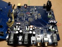
I should have said "the left red arrow marks the capacitor used to bypass the AK4113 DIR."
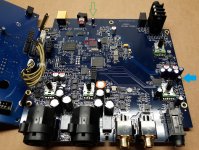
I meant to change the arrow color but it is too late to edit the picture. So I have attached the picture again with a different color for each arrow. I would like to know the purpose of the capacitors marked with the blue and the green arrows.
I meant to change the arrow color but it is too late to edit the picture. So I have attached the picture again with a different color for each arrow. I would like to know the purpose of the capacitors marked with the blue and the green arrows.
Attachments
- Home
- Design & Build
- Equipment & Tools
- E-MU 0404 USB 2.0 and some "artifacts peaks" on left channel