The FETs are obsolete mostly due to the package. Variations are available in SMT. I bought 100 on eBay recently and they test way better than the ones in the older unit I have. Now that I have a Metcal desoldering tool I'm almost ready to swap out 30 FETs. But not quite. . .
I'm looking at ways to sort that are not too difficult. So far what works well is to mount a socket with gate shorted to source through a 5K resistor and then apply 5V AC through 600 Ohms across source-drain and measure the voltage there. Lower is better and use the lowest in series with the lowest value resistors (5K) in the attenuator networks.
I have several of those little all purpose part testers with either multiline or graphical displays, based on microcontrollers, that cost around $15 each. They do R's, Caps, Transistors, and Jfets, using a single voltage and I guess a constant current, probably 5 volts and 1 mA. or similar. Different sets give several different values or parameters on the readout, but all let you select or match parts, for polarity and hfe and likely use 1 mA., or 5 mA. and another voltage, so I suppose their test is somewhat like what you suggested.
Either way, one could select for a particular parameter, high or lower. On caps it gives ESR values and that allows best / mediocre / bad selection, along with uF., very good for grading and matching tantalum caps, and electrolytics. I didn't have any J108's, but previously I matched and tested 2SK170's, and noted that the three testers all give very similar results.
I just ordered a handful of those National J108's just to have them. Reading through the Boonton 1120 and the 1121A manuals it appears that the source (Oscillator) card #112077-00A is, as far as I can tell, the same in my 1120/S10, the 1121, and in the 1121A, all three using the thru pin J108's. I note that on the A6 Oscillator board Q1 is a PN4391A in the 1121A, not sure if it is the same in both my sets, ( yes it is, I just looked!). All the rest of the Jfets Q2 - Q24 are J108's, I wonder if they are matched in some way - for a particular parameter?
All the other cards in the 1121A, use surface mount parts MMBF4391LT1 and MMBJ108's Jfets on other boards that were converted to all smt parts. Maybe there are some minor differences that I did not pick up on, but really the only difference between the 1120/S10, the 1121, and the 1121A seems to be conversion of thru pin parts to smt parts, and that the -5 volt regulator is no longer a TO-3 on the heatsink, but another flat pack type on the inside. Functionally, the differences must be in the software (firmware) as the hardware is quite a constant thing.
Steven
the parameter you are checking for is the on resistance. A 5K resistor tied between source and gate will turn the jfet on and is approx what is used on the PCB. Then you can measure with DC or AC but AC is what its used with. And its easy to measure small AC levels. The on resistance is 5 Ohms or less. There seems to be a correlation between on resistance and distortion so I'm opting for the lowest on resistance.
Regarding the Jfets...
I have been doing a lot of figuring the past few weeks, stuck in the house due to the CoronaVirus being so prevalent here in Queens, everything outside is basically shut down. Thinking about these Boonton units - they really screwed up the power supplies in these sets!
First some background. There are three main voltages, +15, -15, and +5 volts. For whatever reasons the +/-15 are derived from a 4A full wave Bridge followed by a 4,700 uF. / 35 volt Cap feeding both the + and - regulators a 7805 and 7905, with some zeners and feedback Op Amps on the pin to ground so they float. That is OK, and that one cap lowers the AC ripple just enough to give fairly low ripple to ensure the 1 Amp 7805/7905 pair work well enough.
However, the main +5 Volt 3 Amp power comes from U4, an even older technology, obsolete type LM323K in a TO-3 case, on the external side of a large heatsink, which is powered from a SDA-980-1 a 25 Amp bridge, and C18 a 26,000 uF. /16 Volt cap (according to the 1120 manual parts list).
On the hand written 1120 schematic it's even worse, one zero was apparently dropped, on there, making the power supply a 25 Amp Bridge, followed by a 2,600 uF. / 35 Volt cap... Inside the set (in reality) - is a 4,700 uF. +/-20% 35 Volt cap (which might be functionally as low as 3,800 uF. and still be within tolerance, circa 1985... over three decades ago). That is what lowers the ripple inside the Boonton 1120 and 1120/S10 sets, but not enough! No wonder those P.S. caps overheat and keep failing!!!
This "U4" LM323K 5 Volt / 3 Amp regulator needs at least 22,000 to 27,000 uF. upstream on the input side to have sufficiently low ripple in order to operate properly and with best efficiency. I'd recommend a 33,000 uF. / 35 Volt part for C18 if I was refurbishing the set. Yes, that external heatsink gets pretty warm, and it is from that LM323K goin' bonkers!!! This is a Factory Error inside EVERY BOONTON SET.
It gets no better in the 1121, or 1121A which uses C113, a mighty 6,800uF. / 50 Volt cap that is feeding the equivalent of the 323K, an updated LM1085-5 a flat pack, low-dropout modern 5 Volt / 3 Amp regulator, that too should also see 22,000 to 27,000 uF. upstream!!!
My 1120/S10 will have a new 33,000 uF. / 35 Volt C18 cap installed in a few days, when those parts arrive. I wonder if the loopback residual distortion of 0.0022% will be improved, before any other upgrades on the plug-in cards are involved? (still waiting for my extender card to arrive!).
I'll let ya know!
Steven
the parameter you are checking for is the on resistance. A 5K resistor tied between source and gate will turn the jfet on and is approx what is used on the PCB. Then you can measure with DC or AC but AC is what its used with. And its easy to measure small AC levels. The on resistance is 5 Ohms or less. There seems to be a correlation between on resistance and distortion so I'm opting for the lowest on resistance.
I have been doing a lot of figuring the past few weeks, stuck in the house due to the CoronaVirus being so prevalent here in Queens, everything outside is basically shut down. Thinking about these Boonton units - they really screwed up the power supplies in these sets!
First some background. There are three main voltages, +15, -15, and +5 volts. For whatever reasons the +/-15 are derived from a 4A full wave Bridge followed by a 4,700 uF. / 35 volt Cap feeding both the + and - regulators a 7805 and 7905, with some zeners and feedback Op Amps on the pin to ground so they float. That is OK, and that one cap lowers the AC ripple just enough to give fairly low ripple to ensure the 1 Amp 7805/7905 pair work well enough.
However, the main +5 Volt 3 Amp power comes from U4, an even older technology, obsolete type LM323K in a TO-3 case, on the external side of a large heatsink, which is powered from a SDA-980-1 a 25 Amp bridge, and C18 a 26,000 uF. /16 Volt cap (according to the 1120 manual parts list).
On the hand written 1120 schematic it's even worse, one zero was apparently dropped, on there, making the power supply a 25 Amp Bridge, followed by a 2,600 uF. / 35 Volt cap... Inside the set (in reality) - is a 4,700 uF. +/-20% 35 Volt cap (which might be functionally as low as 3,800 uF. and still be within tolerance, circa 1985... over three decades ago). That is what lowers the ripple inside the Boonton 1120 and 1120/S10 sets, but not enough! No wonder those P.S. caps overheat and keep failing!!!
This "U4" LM323K 5 Volt / 3 Amp regulator needs at least 22,000 to 27,000 uF. upstream on the input side to have sufficiently low ripple in order to operate properly and with best efficiency. I'd recommend a 33,000 uF. / 35 Volt part for C18 if I was refurbishing the set. Yes, that external heatsink gets pretty warm, and it is from that LM323K goin' bonkers!!! This is a Factory Error inside EVERY BOONTON SET.
It gets no better in the 1121, or 1121A which uses C113, a mighty 6,800uF. / 50 Volt cap that is feeding the equivalent of the 323K, an updated LM1085-5 a flat pack, low-dropout modern 5 Volt / 3 Amp regulator, that too should also see 22,000 to 27,000 uF. upstream!!!
My 1120/S10 will have a new 33,000 uF. / 35 Volt C18 cap installed in a few days, when those parts arrive. I wonder if the loopback residual distortion of 0.0022% will be improved, before any other upgrades on the plug-in cards are involved? (still waiting for my extender card to arrive!).
I'll let ya know!
Steven
Last edited:
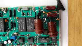
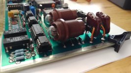
I finally got around to installing lightbulbs instead of R13 and R14 in the input board.
The bulbs were sourced from eBay, they're "Glühlampe E10 23mm 220V 3W" types. The sockets are from eBay too, they're some USSR vintage military Bakelite E10 spring loaded sockets. Wiring is solid copper CAT5e.
I wish I'd taken before and after measurements, but I can provide measurements with and without the 30kHz low-pass filter, maybe someone can fill in the blanks then. With the output high running into the input high via a short BNC cable, I get the following DIST for a 1kHz signal (30kHz vs full BW):
1V 0.001% vs 0.0027%
3V 0.0008% vs 0.0017%
10V 0.001% vs 0.0027%
Attachments
Good work. What is the cold resistance of those lamps? They are smaller than anything I have found so far.
I seem to have run into a limit at .0006% myself. Look at the spectrum on the monitor output to see what the distortion causes are. The light bulbs will lower the noise. More can be done with resistors in the input network to further lower noise. If interested I'll provide the details.
I use an AD797 in U9 because I got lower distortion from it.
Lower noise would always be welcome. Can you give me a rundown of the resistor mods that you've done?
The bulbs' cold resistance measurers 1.28kOhm
I can provide a link of you're interested.
There's one more mod I have to do, iirc there's an opamp that can be jumpered, gotta read through the thread once more. And I gotta say, the analyzer is such a treat to work with.
The bulbs' cold resistance measurers 1.28kOhm
I can provide a link of you're interested.
There's one more mod I have to do, iirc there's an opamp that can be jumpered, gotta read through the thread once more. And I gotta say, the analyzer is such a treat to work with.
Attached are the changes I made to lower the noise. All the resistors need to be .1%. I may have a set left over, I would need to check. Its a pretty simple mod. The input circuit distortion with this mod is significantly lower (in the -120 dB range) than the rest of the instrument so not an issue.
The light bulbs are a problem here. The instrument is designed to handle 240V on its input and the lamps need to handle that before the input ranging switches. 240V miniature lamps are quite rare here (120V country) and the sockets are large and clumsy.
Another really useful mod is to add another BNC on the back and connect it through a 1K resistor to pin 27 (input) to monitor the input signal while the monitor output is looking at distortion.
As a general bench instrument its really nice to use and quick. I have instruments that are better for individual aspects but not as system. The generator is as flat as a precision AC calibrator and the frequency can be set to 5 digits accurately.
Steven's remarks about the power supply have much merit but I don't think ripple on the 5 volt supply will get to any measurements, at least not that I have seen.
Attachments
Dear 1audio,From my last response from Mike I would say yes except when family does the same. But I can relate.
He sent me some detailed involved mods that worked. I can share them with the correction that sent me sideways. Is there interest?
I am currently looking to get an hand on a Boonton 1130.
Would you mind share with me the correction Mr. Lynch has sent you ?
The 1130 is the analyzer section of an 1120. What is curious is that the oldest 1120 I have has always had the lowest distortion floor on the analyzer even stock. The later ones even with mods were not as good. The noise mod above is pretty simple and works. The other mods are quite involved and did not seem to get that much improvement.
What I would suggest is the following-
1) measure the current distortion and noise floor with something like Victor's oscillator so you have a real picture of its current state. Measure at 2.9V before range switching, The noise floor comes up a lot at 3V. Its the input attenuator that limits the performance.
2) the noise mod above is pretty simple (opamps and a collection of resistors) which helps.
3) PM me and I'll send the info and notes. Its a lot of mods to work through and if you are already able to get to .0006% then probably not worth the effort.
I wonder...
The Boonton 1130 distortion analyzer do not have a signal to noise ratio measurement function, contrary to the Boonton 1120 or the Hewlett Packard 8903.
But it seems to me it should be possible to use the Ratio Mode to obtain something very close to a signal to noise ratio. By taking a SINAD measurement of a signal at its maximum level and setting it as reference and after that proceeding to take another SINAD measurement in Ratio Mode at the same frequency but at a signal level on the verge of the lowest sensitivity range (or perhaps a little higher?) of the analyzer, where the harmonically related content should be buried under the noise floor, it might be possible to obtain a difference value representing only the signal to noise at this level, and then compute the numbers to obtain something very close to a linear signal to noise ratio.
Has anyone ever try to use a Boonton 1130 in such a way ? Is the idea relevant ?
Not trying to hijack. Found this thread trying to revive my 1121. Lots of good info. I also laid out and am currently making extender cards as mine was missing. I will end up with 8 spares I will share once done, and will offer for much less than the ransom I found for the ones on Ebay and elsewhere. Lordy. I have the same oscillator errors as listed earlier so something with the source signal chain. I am using this piece of gear to teach my Tech about troubleshooting because it is so easy to work on and there's little danger of spring probe cataclysmic shorts like on high density SMT designs. I used to use this piece of gear to characterize VLF receivers back in the day. Been gathering dust in my rack for a few decades. Will be glad to have it back in service. Did the replug of the socketed parts to no avail. Time to start probing. And then hopefully modifying!
I just got a Quant Asylum 403 audio analyzer, so I am testing my Boonton 1110 oscillator, which shares nearly the same "Source" board as the 1121a.
Without any tweaks, the Quant tells me -103dB THD, "High" output, float not engaged.
With new electrolytic caps everywhere (except the extra-large psu filter caps), I get -106dB... a -3dB improvement.
But I am not understanding something about the 1110.
In "floating mode", shouldn't I be seeing (on my scope) the "high" and "low" as a sine and cosine of equal value ?
I tried simple BNC cables between instruments, and in one photo below, I connected a seperate ground to a Boonton internal board Ground point.

The output is actually "bridge tied" and the whole circuit floats when in single ended. Its sine plus inverted sine. Opamp upgrades help and are simple but the big limitation is the analog multipliers. Finally the FET attenuator is a limitation. Still you should be able to get to -106 dB THD=N in a 30 KHz band. Float the output and tie the ground of the chassis to the QA403. and check where best to tie the low side of the output. You will need to experiment since there will be ground leakage that limits the system noise. A real PITA to pin down and impacted by every connected device.
PS your logo is the Dymec logo? Old HP subsidiary? https://www.hewlettpackardhistory.com/item/turning-hp-upside-down/
Just having a single-ended LDO is fine by me !
Although I was hoping for a good "balanced" signal to send through my balanced audio gear, for testing.
I want to be sure this is a proper signal for that purpose. I would like to wire an adapter from the oscillator to an XLR connector, and I am not 100% sure of the correct connections.
On my Source board, there is an OPA27fz instead of the original OP07ep. I may have swapped those years ago ??
I tried an OPA227 in there and it made things a lot worse.
On that board I also swapped the good Signetics NE5532a's for OPA1602's on adapters, and saw a slight improvement (.5dB ? ), but I switched them back.
I have some OPA1611 singles on order to swap for the NE5534"s on the amp board, but we'll see. The 5534 is hard to beat, plus whether to keep (or short-out) their compensation caps is an unknown for me.
RE: my avatar..... No, I did not realize that Dymec/Dynec found a similar use for the HP logo. I discovered on my own that the upside down "hp" could read "diy", if I graphically altered it so there became an apostrophe on the upturned " p ".
- Home
- Design & Build
- Equipment & Tools
- Boonton 1120/1121 Distortion Analyzer tweaks