I posted on another board my adventures tweaking the 1121 to get a lower distortion floor. The notes are here: diytube.com • View topic - Boonton 1120/1121 upgrades
The analyzer now reliably nulls to .0005% THD. This is a substantial improvement.
The analyzer now reliably nulls to .0005% THD. This is a substantial improvement.
Hi 1Audio,
The reason I'm asking is I've found, for lower levels 5Vrms down, the LT1468 to out perform the LME series and 5534 op amp(s). They are are a bit fussy to use, (parasitic oscillation), but once cleaned up.... LT's 1468 data sheet and design notes show how to handle this.
Might be worth a try.
Cheers,
David.
That is a really interesting IC. I'll get some to play with. Cheaper as well. Unfortunately the 1121 uses duals in those locations. Either will probably pass the signal with harmonics well below -120. The bigger issue I think may be common mode induced distortion, something missing from all the datasheets. . .
I would like to find a chip (dual) with really low common mode induced distortion. But that all pales before using a Tantalum coupling cap with no DC bias.
I would like to find a chip (dual) with really low common mode induced distortion. But that all pales before using a Tantalum coupling cap with no DC bias.
Hi Demian -- the LT1468 comes in a dual, the 1469, and they really are good. RE common-mode distortion, I've found the summing amps in most notch filter designs to be a big generator of 2nd harmonics -- which I'm sure is CM distortion.
Jim Williams floated the idea of an amp to provide a floating, driven common-ground point in his Wien bridge oscillator in Fig. 47 (write-up on this says it's for fig 48, but somebody swapped the figures) in Linear's App note 43. That may work -- I'd like a fix for this problem in my HP 339 without having to rebuild the entire notch filter.
And Doug Self proposed a way to signal-modulate the power supply used with FET-input amps to minimize input capacitance modulation distortion. Can't at the moment remember where I saw that, but I think it was in a series of articles in EDN or some such trad magazine.
That is a really interesting IC. I'll get some to play with. Cheaper as well. Unfortunately the 1121 uses duals in those locations. Either will probably pass the signal with harmonics well below -120. The bigger issue I think may be common mode induced distortion, something missing from all the datasheets. . .
I would like to find a chip (dual) with really low common mode induced distortion. But that all pales before using a Tantalum coupling cap with no DC bias.
Ah. dual version is the LT1469.
The LT1468/1469 have a much lower current noise density than the LME. For source resistances in the range of 1k to 20K the voltage noise is the same or higher.
At 3Vrms or lower the distortion at 1KHz approaches the floor of an EMU 0204 fundamental suppressed <= -60dB. Should be similar to your demo board.
For source resistances below 1k I've been looking at the OPA1642/1641 at about the same price of a 1468/1469.
Cheers,
David.
Jim Williams floated the idea of an amp to provide a floating, driven common-ground point in his Wien bridge oscillator in Fig. 47
Hi Dick,
Is this a virtual ground?
I'll take a look.
David.
updating my notes-
I can now get reliably -106 dB THD with either input live. The key update is changing U9 to an AD797. It does drop in and work. Expect to do a recalibration and CMRR adjustment. I also replaced U5 and U8 with LME49710's. I have tried the AD797 but something was not happy since there is no series resistor from out to -in. I'll explore after the following.
However the whole input is limited by noise. I'm going to redo an extra input board with new values that should get 10-20 dB lower noise. Its a festival of .1% resistors and the real question is whether the lower values will trade noise for increased harmonic distortion. The other challenge is replacing R13 and R14 with light bulbs. I have found the pieces and I know the lower series resistance will help. Grafting them into the board will be the challenge.
richie:
if i don't misunderstand what you mean, i am thinking you refer instead to walt's paper from his time at analog devices:
mlloyd1
if i don't misunderstand what you mean, i am thinking you refer instead to walt's paper from his time at analog devices:
mlloyd1
...
And Doug Self proposed a way to signal-modulate the power supply used with FET-input amps to minimize input capacitance modulation distortion. Can't at the moment remember where I saw that, but I think it was in a series of articles in EDN or some such trad magazine.
Has anyone worked on improving the audio oscillator of the Boonton 1120/1121?
I just joined diyAudio a couple of days ago and noticed some nice work on lowering the residual distortion of the Analyzer section. I designed these products for Boonton back in the 80's and plan to take a look at improving them with modern components. Let me know what you found. There is room for improvement and I do not take it personally, when others improve on my work. I encourage it.
Ever wonder why it is designed the way it is? I am to blame.")
I designed all the analog, digital and embedded software and wrote the manual. I did not design the mechanical package, though. I can help answer your questions and maybe together we can make it even better.
I have to say that those years were the most fun and rewarding I have had my whole career. Initially component swaps and minor tweaks may be attempted, but I would not rule out designing new boards too. I have both an 1121 and an 1120-S/1 and some extra boards to start off.
Let me know what you would like to achieve. Nothing is off the table. Let's talk and see where it leads.
I just joined diyAudio a couple of days ago and noticed some nice work on lowering the residual distortion of the Analyzer section. I designed these products for Boonton back in the 80's and plan to take a look at improving them with modern components. Let me know what you found. There is room for improvement and I do not take it personally, when others improve on my work. I encourage it.
Ever wonder why it is designed the way it is? I am to blame.
I designed all the analog, digital and embedded software and wrote the manual. I did not design the mechanical package, though. I can help answer your questions and maybe together we can make it even better.
I have to say that those years were the most fun and rewarding I have had my whole career. Initially component swaps and minor tweaks may be attempted, but I would not rule out designing new boards too. I have both an 1121 and an 1120-S/1 and some extra boards to start off.
Let me know what you would like to achieve. Nothing is off the table. Let's talk and see where it leads.
I have been contributing the most I think. I did do some tweaks (parts swaps) on the oscillator as well but switched to the analyzer focusing on it first.
Its a remarkable package and if you did it all I'm really impressed. Boonton must have given you a fair amount of freedom and time to do it. They are still selling them many years later so it was a good move on their part.
If you have the firmware source that would be great. I have always wanted it to come up in balanced/isolated on reset. Replacing the ground fuses is not real easy. And being able to select specific input ranges or at least displaying them will make readouts on an external FFT much more useful.
I have been really impressed with the performance overall. Even though I have had 2 Shibasoku analyzers on the bench and a half dozen more in storage the Boonton has been the one that got results the fastest and stayed on the bench for daily use.
My last efforts on the analyzer input were to re-scale the impedances down (10:1) to get the noise floor down. I made some progress but seemed to run into a wall elsewhere. The common mode rejection went way up however.
Ideally I think it should be possible to get close to the AP 2722 specs given the performance possible with the latest audio opamps. Big questions revolve around where the distortion is limited. From what I have seen the input differential amp should be good for -115dB or better. Probably better than that but the noise is a limitation. The 400 Hz high pass filter is an issue since it creates distortion at around .0015%. Probably common mode issues. The notch filter is the real unknown. The analog multipliers deliver remarkable performance untrimmed but they could be a limitation. They have been discontinued so a new solution may be required anyway. I don't think the FET switches are an issue at this level. I think the oscillator is similar on the analog multipliers. The disciplining against the reference clock works really well and makes it one of the cleanest low frequency synthesizers I have encountered. The flatness is on a par with a precision calibrator (before the output resistors). The output amp needs to be looked at. On the first gen with the 3V output its quite clean box stock. The later ones (16V) seem to have some distortions either in the attenuator or more likely the amplifiers. Its a good circuit but needs to be better. Its more of a pain to work with mounted on the back of the box.
As you know the mechanicals are fragile but they can be bent back into shape.
I think I have 4 or 5 of them in my collection and a set of extra analog cards. I can explore ideas you may have and would help however I may.
Hi Demian,
Thanks for the reply and your kind words about “my children”. Yes, you have been doing some really fine work on improving the performance. You know the box quite well and have identified many of the design improvement areas. Maybe I should contact Boonton and get their wish list too
First a little history:
I grew up in Parsippany NJ and so I had plenty of opportunities for summer jobs at many great names in the test and measurement industry. When I got my engineering degree, I had 3 offers within 2 weeks of graduation within easy commuting distance of my home. Boonton was the best choice since they offered me the opportunity to pursue whatever discipline I wanted and they had a broad product offering. The company was always fairly small. There were about 150 people there in the early 80s and the senior engineering staff had many talented engineers that had worked previously at the renowned Boonton Radio Corp, which was acquired by Hewlett Packard earlier. Many of these folks eventually left the big HP and their careers led back to Northern NJ and Boonton Electronics. It was the ideal place for a young engineer, fresh out of school, to learn good practices from great mentors.
I was given a free hand after a couple of years’ experience. Boonton made RF signal generators and RF modulation analyzers at the time. Together, both products had audio in/out connections and we would always use the HP8903 in system setups. HP was our primary competitor for signal generators and modulation analyzers and it seemed like we were missing the audio product. I suggested to the Marketing and Engineering VPs to let me see what I could do with a distortion analyzer and that is when the original model 1120 was developed. It was very successful and so I was able to make improvements to roll out the 1120 S/1. (‘S/#’ is the Boonton method of indicating a special version or significant modification) The S/1 had a complete upgrade of the power supply and source output circuits to drive 8V rms in 50 ohms and the ability to completely float the source off chassis ground. The next upgrade was the 1120 S/10 for the military that had improved Mean Time Between Failure (MTBF) performance. Then came the 1121 with upgrades to the analyzer section. We added the CCIR filter and the quasi-peak detector and included an additional gain stage after the notch filter to improve sensitivity in AC level and Distortion measurements. This additional stage is what makes it possible to take advantage of lowering the distortion residuals. We get an extra digit!
You have suggested a lot of good ideas. The multipliers are a weak part. They add 2nd harmonic distortion and I had worked on replacing them before I moved on. Somewhere there was a board with new multipliers, dead bug style that had THD+N running around 0.006%, but it never made it into production. This is one place I will revisit after swapping out the old for new op-amps.
The input noise was well known and it was difficult to meet the 300V rms input specification with lower impedances. One application for the product was to monitor distortion on power lines. I would like to take a second look at the whole input board later and cut out 30% of the components. This would be a new board design so it will have to wait until after “picking the low-hanging fruit”. For now, there are some improvements that can be done with the existing board.
I do not have the firmware. It belonged to the company and the development system was proprietary. We used to roll our own back then. I do have an idea about changing the initialized state. I do not have the tools to do it yet (no IEEE-488 interface controller), but it will involve reprogramming the PROM after altering two bits! There is a table in the PROM that has the memory image of the initialized state that is copied into the RAM and is then written to all the latches and displays. Finding the location in the PROM and swapping the state of the bits is the challenge. You can get a copy of the initialized image over the IEEE-488 bus by using the “TL”, Talk Learn String bus command. Once you have a copy of the string, you can search the PROM for its location. Here is how I would do it:
1) Initialize the 1121
2) Set the talk mode to “TL”
3) Retrieve the string from the IEEE-488 bus and save the string (it is the hex values in ASCII format)
4) Turn on FLOAT on both the source and analyzer (and any other setting you want to change)
5) Repeat step 3
6) Search the PROM image with a device programmer for a match of the initialized image. I believe there should be only one match, but I am not sure. Do not forget to convert the ASCII to Hex. I do not know the base address for the initialized state otherwise I would give you the bits to change. Maybe if I get the tools, I will look at this first. The memory address may change with different firmware revisions.
7) Replace the image in the PROM with the new image from step 5
8) Program the PROM and reinstall it on the CPU card. You may want to use a second PROM for this to keep the original unaltered.
9) Cross your fingers and press the INIT key. J
I am sure there are a number of components that are becoming difficult to obtain and those will be on my list as well. For now, let’s keep in touch and I will let you know how things progress. I am going to place an order for a number of single and dual op-amps and start with them.
It will be fun!
Mike
being able to select specific input ranges or at least displaying them will make readouts on an external FFT much more useful.
Table 3-4 in the 1121 Manual shows the available input level ranges and paragraph 3-65 describes how to set input level ranges. There are similar tables and paragraphs in the 1120 and 1130 manuals, but the values may be slightly different at the highest sensitivity ranges. You can hold the current range where it is by entering SPCL function 11 (LEVEL) or 12 & 13 (DIST/SINAD). But what I believe you want to do is set the range and hold it. All you need to do is select the measurement function and the KYBD light will indicate that the keyboard is assigned to the active function in that left side display. key in the value of the input range and press 'V' or 'mV' and the analyzer will set the range appropriate for the value entered and automatically set the SPCL function to hold it there. In the DIST modes, the input ranges before the notch filter are set independently from the output ranges after the notch filter (SPCL 12, 13). You set the output ranges in a similar fashion by entering values in % or dB. The SPCL light will stay on in the center display to show that the unit is operating in range hold mode. Switching to a different measurement function clears the range hold and extinguishes the SPCL light. Also entering SPCL 10 clears all special function 11-18 in one action.
Example 1: if you are in the LEVEL mode operating at 2Vrms input and want to set the MONITOR output for unity gain through the box, you can enter any value between 1.501 and 3.000 V and it will set the 3V range.
Example 2: if you are in the DIST mode operating at 2Vrms input and want to set the MONITOR output for unity gain through the box before and after the notch filter, you can enter any value between 1.501 and 3.000 V and it will set the input 3V range and then enter any value between 50.01 and 100% to set a gain of x1 after the notch filter. Table 3-5 lists available output gain stage selections.
BTW, entering the frequency in the DIST mode sets the notch filter nominal center frequency (auto-tune takes over from there)
Unfortunately, you cannot display the range value entered. If in doubt, enter the values again. One last point, the input-overload window detectors override any range hold setting to protect the front end.
Hope this helps.
1120-1121
I bought my first 1120 in the end of -88, beginning of -89, if memory doesn`t completely fail me. It was replaced a couple of years later by Panasonic VP-7722. The latter one had provision for also showing 2-5 harmonic separately, which I found very useful.
I still missed the clean and simple layout of the Boonton though, in my view way better than the Panasonic. However, the latter had much better specs, so I continued to use it up to about five years ago, when it ultimately were replaced by a R&S unit
I still have a couple of 1120 / 1121 on my shelf somewere, and I would be very interested in "revamping" these nice machines, especially if all the aforementioned bugs could be ironed out, and, preferably, with improved specs.
I derived great pleasure in your history recap Mike, and who would be more motivated to correct old mistakes if not "the original father"?
Regards
Roar Malmin
Thanks RM!
I ordered a bunch of AD797, LME49720 and LME49710 parts last night to get started. Almost picked up some four-quadrant multipliers, but decided to wait and until after I evaluate the op-amps. Multipliers are expensive! I had experimented with MPY634 back in the late 80s with good results. I am looking at specs and sources for the SW-06 as an alternative, but have not ordered any yet. I should have used discrete FETs instead of the LF1333 or put the gain up front on the Input Card. I will probably start by removing the LF1333 and fix the gain at unity for initial measurements. I will be working on the 3V input range anyway so the switch won't be needed.
On the notch filter, there is a jumper that may be removed to disable the auto-tune and auto-balance. This should remove any 2nd harmonic from the multipliers and pulling out the comparators should prevent any switching transients from adding distortion too. I should be left with a much cleaner manual-tune notch filter to knock down the fundamental and view the harmonics on an external RTA at the MONITOR output.
Once I get the Analyzer section down to where I want it, I will shift my attention to the source side.
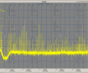
Below is the distortion residual at the output of the input board. Source is a modified KH4400 and the analyzer is the Shibasoku 725. The markers are on the distortion products. It also shows all the common mode noises in my setup. Most are post analyzer stuff. The levels are scaled property and can be read on the markers. The 2nd and 3rd harmonics are at the -125 dB level.
I can send you the modified board if you would like. I scaled all the resistors in the differential amp by .1 and got .1% resistors for the existing .1% parts. The 10K resistors on the input, R13 and R14 I replaced with light bulbs to get a much lower resistance and noise. in normal operation.
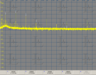
The second image is the monitor out under these conditions. It reports -104.4 dB under these conditions. This is where the scaling becomes an issue. The relative levels are easy but absolute levels are not.
I can send you the modified board if you would like. I scaled all the resistors in the differential amp by .1 and got .1% resistors for the existing .1% parts. The 10K resistors on the input, R13 and R14 I replaced with light bulbs to get a much lower resistance and noise. in normal operation.
The second image is the monitor out under these conditions. It reports -104.4 dB under these conditions. This is where the scaling becomes an issue. The relative levels are easy but absolute levels are not.
Attachments
- Home
- Design & Build
- Equipment & Tools
- Boonton 1120/1121 Distortion Analyzer tweaks