Yes, it helps to set the lowest distortion (and I don't remember now about a voltage level). I had assembled this oscillator two times (with 2N5484 instead of 2SK30), and after the adjustment both pots were very close to the middle. So, I am 95% sure the pot can be changed to a constant resistor with a similar equivalent resistance. I think we can just get rid of that VR pot and we may have only R8, R9 1k left.distortion can be set to minimum.
It probably also influences the output level.
R3 (120-150k) can be reduced to 27-30 k with almost proportional distortion reduction. With R3 = 120-150k I had 0.006% THD as specified, but with R3 = 27k I had about 0.001% (at 1kHz and OPA2134).
C3 must be twice as larger as C4 (+-5%). This insures the best overall performance.
Last edited:
Yes, it helps to set the lowest distortion (and I don't remember now about a voltage level). I had assembled this oscillator two times (with 2N5484 instead of 2SK30), and after the adjustment both pots were very close to the middle. So, I am 95% sure the pot can be changed to a constant resistor with a similar equivalent resistance. I think we can just get rid of that VR pot and we may have only R8, R9 1k left.
R3 (120-150k) can be reduced to 27-30 k with almost proportional distortion reduction. With R3 = 120-150k I had 0.006% THD as specified, but with R3 = 27k I had about 0.001% (at 1kHz and OPA2134).
C3 must be twice as larger as C4 (+-5%). This insures the best overall performance.
This technique was pioneered by Hewlett Packard for their oscillators in the mid 1960's when JFETs began to be used for gain control applications. Theory does indeed say that the AC drain-source feedback to the gate should be 50%, but I have sometimes noticed that a slightly different value is optimal. In my THD analyzer, where I use this technique in both the oscillator and state variable filter auto-tune circuits, I use a trimmer for the feedback value. However, one can usually get quite close to the optimum by using a 50% value implemented with precision resistors.
Cheers,
Bob
This took me a moment to recognize in that circuit. FET attenuators often have a two-resistor network that reduces distortion of the attenuated signal, versus just a straight DC voltage on the gate. It's discussed in "The Art of Electronics" 2nd and 3rd editions, and (from googling) here in fig 6:Yes, the 'normal' procedure for lowest distortion would be to add half of the signal across the FET to the gate.
Jan
https://www.vishay.com/docs/70598/70598.pdf
I recall that the resistor value used is rather high, in the 100k to 2 meg range. The text mentions 470k. I don't recall, but I would imagine this circuit is discussed earlier in the thread.
In the oscillator circuit posted, The lower left op-amp buffers the AC drain signal, and the lower right op-amp provides the DC level proportional to signal output voltage. Since both signals are op-amp outputs, the resistive mixing circuit can use lower value resistances.
For what it's worth, I found this in my search results, a 'balanced' attenuator that cancels 2nd harmonic distortion. If you have matched FETS and extra op-amps, this might be useful:
https://www.edn.com/a-guide-to-using-fets-for-voltage-controlled-circuits-part-1/
https://www.edn.com/a-guide-to-using-fets-for-voltage-controlled-circuits-part-1/
For what it's worth, I found this in my search results, a 'balanced' attenuator that cancels 2nd harmonic distortion. If you have matched FETS and extra op-amps, this might be useful:
https://www.edn.com/a-guide-to-using-fets-for-voltage-controlled-circuits-part-1/
Thanks for that. I see a lot of these circuit variations in FET compressor / limiters. Sometimes you actually want the extra distortion, sometimes not.
To have a circuit that can morph between a few of these would be cool, to make it creatively and easily usable by a non technical person is the real challenge.
TCD
New revision of the oscillator board has been made. Now the AGC fet is connected to the non inverted input of the opamp. This configuration is less sensitive to interference, less parasitic capacitance at the inverted input of the opamp and also the signal over the fet can be two times lower due to the non inverted gain of the opamp.
Vic.
Vic.
Attachments
The limited Ohmic range of a FET means you have to trade distortion for noise. An LDR coupler is better for higher signal levels. For an oscillator where there is no attack dynamics, I would use an LDR. HP's original product used an incandescent lamp cold vs hot resistance. But for my purposes, a 10+ bit DDS is more stable and precise, maybe with a bit of tracking filter. Using a PLL can make a tracking filter that is not dead reckoning. Performance is quickly limited by the op-amps or other amplifiers.
Last edited:
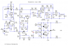
I have been using Victor's generator for several months and finally decided to measure it. It's output is configured in balanced mode. Negative output is taken from pin 7 of OPA1656. The setup is - Vic -> 40db -> 20db amplifier. At 1V RMS and 1.5V RMS generator output level no harmonics are visible. ") At 2V RMS a tiny third harmonic is observed at around -125db. 5db added and 20 removed and the real 3rd harmonic level should be around -140db.
At 2V RMS a tiny third harmonic is observed at around -125db. 5db added and 20 removed and the real 3rd harmonic level should be around -140db.
At 2V RMS a tiny third harmonic is observed at around -125db. 5db added and 20 removed and the real 3rd harmonic level should be around -140db.Attachments

10x ! The mains are low, because everything is balanced.
OPA1642 2x10 in parallel. Amplification of 10 (not 11). The FB resistor is corrected. https://www.diyaudio.com/forums/ven...ormance-cmos-audio-op-amp-43.html#post6558798
The mains are low, because everything is balanced. OPA1642 2x10 in parallel. Amplification of 10 (not 11). The FB resistor is corrected. https://www.diyaudio.com/forums/ven...ormance-cmos-audio-op-amp-43.html#post6558798
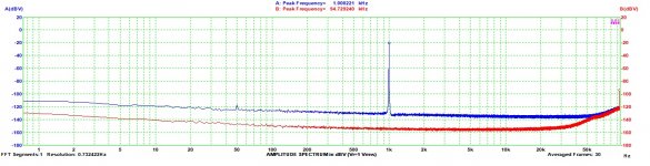
And another round of measurements. Now with 70db notch and 20db + 50db amplification. 50db with OPA1612.
AT 1V RMS I am amplifying only the noise of the notch. The Vic generator cannot be measured with my setup. At 2V RMS the tiny 3rd harmonic is seen as in the first measurements but amplified 50db more. It is below -75db. So - 5db for the notch and 70db lower. It is below -140db.
And this is at 2V RMS. At 1V - nothing ! Just noise
Attachments

10x !
OPA1642 2x10 in parallel. Amplification of 10 (not 11). The FB resistor is corrected. https://www.diyaudio.com/forums/ven...ormance-cmos-audio-op-amp-43.html#post6558798
That's ... heroic!
Jan
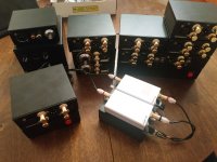
Glad, that you liked it ! As Victor mentioned shielding is important.
Every amp, generator or power supply is put in an aluminum box.
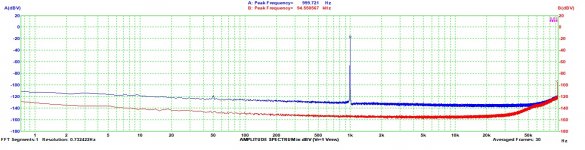
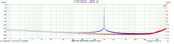
This is a direct measurement. Red - the noise floor of the setup. The blue spectrum - 1V RMS Victor generator. These are the limits of the system. The third harmonic is from the setup. Victor's generator is not to blame.
Every amp, generator or power supply is put in an aluminum box.
This is a direct measurement. Red - the noise floor of the setup. The blue spectrum - 1V RMS Victor generator. These are the limits of the system. The third harmonic is from the setup. Victor's generator is not to blame.
Attachments
Last edited:
ADC AK5572 v1.2 available – nihtila.com
Very nice guy ! And very good ADC !
Very nice guy ! And very good ADC !
Congratulations on the equipment and measurement results!
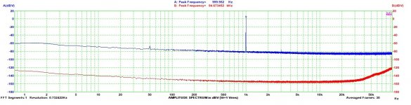
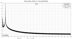
Victor's oscillator is indeed of reference quality - mine is five years old, and this is what I recently measured.
The setup was Groner's notch filter (-100dB) and Groners's LNA from Linear Audio Vol. 3.
The spectrum was taken at 1Vout: nothing to measure
 .
.
Regards,
Braca
Victor's oscillator is indeed of reference quality - mine is five years old, and this is what I recently measured.
The setup was Groner's notch filter (-100dB) and Groners's LNA from Linear Audio Vol. 3.
The spectrum was taken at 1Vout: nothing to measure
Regards,
Braca
Attachments
- Home
- Design & Build
- Equipment & Tools
- Low-distortion Audio-range Oscillator