Methinks the circuit from #9142 is the best.
Coils can be mechanically small and shielded, so they do not pick up hum.
In the series resonant circuit, there is current only at the harmonic, and it
could only generate harmonics of the harmonic it is tuned to, and you could
simply ignore it in the spectrum if it really showed up. I covers nothing. Same
goes for hum pick up.
And the good thing is: the less harmonic you have from the start, the less
flux you have on the harmonic frequency and the reduction on harmonic's
harmonic is even stronger than linear.
There is virtually no current of the fundamental in a series tuned circuit
for the harmonic and thusly no non-linear flux that could generate harmonics
of the fundamental of it's own.
The necessary size of the inductors is greatly overestimated, but I think that
ETD58 cores for 200W switchers would not be a serious burden, mechanically.
The air gap is inside, holster up the middle of the coil to avoid eddy currents
in the copper. They are mostly self-shielding.
I had even decent results with crystal notches removing phase noise sidebands
from an oscillator. And crystals have 20 Ohm series resistance on a good day,
so you need to start at much higher impedance to get an effect. You can apply
power levels that would explode the crystal if you would hit the offset it is tuned to.
Just stay off-resonance with the carrier.
Gerhard
> Me thinks the circuit from #9142 is the best.
You would need to know the Zout of the DUT exactly and compensate for it, not ?
The Zout of the generator. The more, the deeper and narrower is the notch.
You lose if the DUT has a Zin of 0. But that is not an interesting DUT.
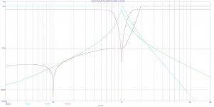

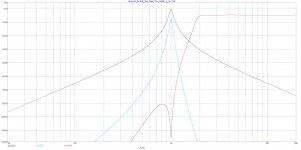
Evolution of the oscillator post filter...
Lowpass followed by bandpass. -110 dB for h2, -150 dB for h3 + hum rejection.
I think a single higher order bandpass would´t get there so easy, did not try yet.
Just put the existing filter in series, practically a less steep version with 2 inductors for lowpass and 2 for bandpass would be ok.
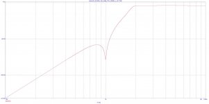
Maybe similar for the pre analyzer filter, combine notch with highpass
Lowpass followed by bandpass. -110 dB for h2, -150 dB for h3 + hum rejection.
I think a single higher order bandpass would´t get there so easy, did not try yet.
Just put the existing filter in series, practically a less steep version with 2 inductors for lowpass and 2 for bandpass would be ok.
Maybe similar for the pre analyzer filter, combine notch with highpass
Attachments
Well that is very, very good! How would this look physically?
Jan
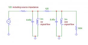
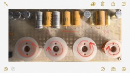
4 x 3 mH inductors mounted flat in a row.
Signal flow cw - ccw - cw - ccw to avoid hum pick up.
together with styroflex caps in a shielded case, clear distance to steel an alu around at least 7 cm.
Now I remember seeing this earlier:
This MAY cancel the hum, but putting the coils next to each other couples them together, making a transformer. These are no longer separate inductors, and any signal in one affects the other. This is going to substantially change the filter response and make it something other than intended.
Air-core coils (or any coils not magnetically enclosed, like a toroid core) in a circuit are usually set with their axes at 90 degrees to each other, to reduce coupling as much as possible.
If a LC filter for example had 2 equal inductors in series, could the picked up hum be eliminated by having the signal going through the inductors 1 time clockwise and 1 time counterclockwise, inductors mounted side by side ?
This MAY cancel the hum, but putting the coils next to each other couples them together, making a transformer. These are no longer separate inductors, and any signal in one affects the other. This is going to substantially change the filter response and make it something other than intended.
Air-core coils (or any coils not magnetically enclosed, like a toroid core) in a circuit are usually set with their axes at 90 degrees to each other, to reduce coupling as much as possible.
Resonances on the fundamental are contra-productive because they
maximize the coil current and off-resonance you get only 1-pole attenuation.
Harmonic notches are exited with 80-120 dB less, so you get away with much
smaller coils and more attenuation for the resonance.
Gerhard
maximize the coil current and off-resonance you get only 1-pole attenuation.
Harmonic notches are exited with 80-120 dB less, so you get away with much
smaller coils and more attenuation for the resonance.
Gerhard
Now I remember seeing this earlier:
This MAY cancel the hum, but putting the coils next to each other couples them together, making a transformer. These are no longer separate inductors, and any signal in one affects the other. This is going to substantially change the filter response and make it something other than intended.
Air-core coils (or any coils not magnetically enclosed, like a toroid core) in a circuit are usually set with their axes at 90 degrees to each other, to reduce coupling as much as possible.
In the picture is my DAC lowpass filter, still has no box after 10 years and collecting dust... spacing between coils outer windings is 2 cm and the filter response is ok.
For outside the box testing or if shielding does not remove hum completely, I would try connecting the coils as the red arrows are showing in the picture.
Attachments
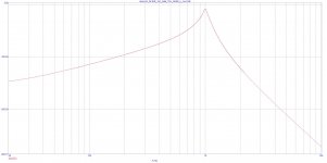
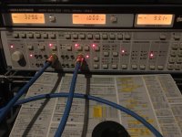
black curve simple osc post filter for testing...
Now I make this simple filter, report later.
Another idea:
1 MHz crystal oscillator, divide down to 1 kHz, cut to desired level, filter to sine wave.
First filter by opamps, final stage passive. Costs nothing.
Last edited:
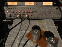
My analyzer‘s generator directly to THD input is around -93 dB
With simple 2-inductor bandpass (a few Hz off) is -115dB to underflow (> -120 dB)
THD display of this Analyzer gets unstable below -95dB
So, with the filter, distortion is at least 25dB better.
In Simulation h2 -30 dB, h3 -40 dB
With simple 2-inductor bandpass (a few Hz off) is -115dB to underflow (> -120 dB)
THD display of this Analyzer gets unstable below -95dB
So, with the filter, distortion is at least 25dB better.
In Simulation h2 -30 dB, h3 -40 dB
Attachments
Last edited:
Better, use two crystals 1 KHz apart and a balanced mixer. All the harmonics will be from post mixer issues. Not original, it's the principle of the GR BFO, which was at its time a very low distortion oscillator.Now I make this simple filter, report later.
Another idea:
1 MHz crystal oscillator, divide down to 1 kHz, cut to desired level, filter to sine wave.
First filter by opamps, final stage passive. Costs nothing.
Better, use two crystals 1 KHz apart and a balanced mixer. All the harmonics will be from post mixer issues.
... or from intermodulation in the mixer ( 2f1 -2f2 etc )
- Home
- Design & Build
- Equipment & Tools
- Low-distortion Audio-range Oscillator