Yes I got the same numbers. It seems about standard for a passive twin-tee notch.
I've been playing with a post-notch amp that amplifies the second by 10dB and the 3rd by 6dB, then returns to 'flat'. Not sure it is worth it.
Jan
This actually sounds like a good idea. I've toyed with this idea as well, but have not done anything with it. A highpass filter with a peak at 2 kHz might be one approach, but I'm not sure if the Q could be adjusted in such a way that the needed gain at 3 kHz was achieved without additional shaping circuitry. A useful objective is to achieve the overall shaping without degrading the notch depth. There is a decent chance that the peaked high-pass filter would actually improve notch depth. It also seems reasonable that achieving overall flatness at frequencies other than the 2nd and 3rd harmonic may not be that important.
Cheers,
Bob
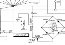
This is the harmonic generator in the Radiometer CLT-1 used for checking the harmonic level calibration. The whole circuit is spread across several scans and can be quite hard to follow. Its quite similar to Victor's implementation. The key is standardized levels for both fundamental and harmonic. When I was checking the Shibasoku it was clear that the impedances and mixing networks were critical to get an accurate harmonic level. Not working it all out can easily get an unintended 6 dB error.
Attachments
I did realize that with the AP, and probably also with ARTA/soundcard, it would be simpler to set up a multitone-waveform with the necessary harmonics and levels, even with defined phase relationships.
It would probably not automagically scale with fundamental frequency so you'd need separate files for say 1kHz, 5kHz, 10kHz fundamentals, but it might be easier to handle in practice.
I'll see how that would work as soon as I get some spare time ;-)
Jan
It would probably not automagically scale with fundamental frequency so you'd need separate files for say 1kHz, 5kHz, 10kHz fundamentals, but it might be easier to handle in practice.
I'll see how that would work as soon as I get some spare time ;-)
Jan
This simple schematic probably can be used for to test the harmonic measurement levels, directly or via the notch filter.
The simulation shows these harmonic levels across the D1 diode rated to the input signal 2,7V RMS (my oscillator max output):
Fundamental -11,6 dB
Second -27,4 dB
Third -27,5 dB
So, the second and third have almost the same levels. These levels can be adjusted more equal with the resistor R2 via the direct measurement, if needed.
The levels at "out1" would be for -80dB lower, and "out2" for -40dB else. Finally, the second and third would be around -147,5 dB.
Now the simulation was tested on the real prototype. It looks like extreme "High End"
") I needed to remove all copper traces, exclude ground, on the prototype board to eliminate the parasitic capacitances :
I needed to remove all copper traces, exclude ground, on the prototype board to eliminate the parasitic capacitances :https://content23-foto.inbox.lv/albums/v/viccc/HCT/HSimP.jpg
I placed one capacitor in the final schematic for to remove the DC from the output:
https://content23-foto.inbox.lv/albums/v/viccc/HCT/HCF.png
The measurement results are perfectly the same as simulated. That was good test for my measurement set up, and for to know how the real things work.
The measurement with the notch, FFT length 524288, 3 times averaging, sample rate 96kHz (the scale was adjusted to read the third harmonic without calculations):
https://content23-foto.inbox.lv/albums/v/viccc/HCT/HSimN.jpg
In the same measurement chain without the notch (removed and shorted):
https://content23-foto.inbox.lv/albums/v/viccc/HCT/HSimD.jpg
I have not seen any smoothing or smearing effects. The oscillator was warmed up before the measurements, of course.
Using a decent soundcard as a DDS source is worth considering. You can add a narrow band filter(s) on the output to remove spurs from the DAC. The DDS approach is good for low phase-noise, but not so good for a low noise-floor.
Any signal generator can be transformed to a low-distortion oscillator using a tunable band-pass or low-pass filter, note. The low-pass is perhaps the easiest to realize well, and a resonant low-pass is even better.
Any signal generator can be transformed to a low-distortion oscillator using a tunable band-pass or low-pass filter, note. The low-pass is perhaps the easiest to realize well, and a resonant low-pass is even better.
Now the simulation was tested on the real prototype. It looks like extreme "High End"
https://content23-foto.inbox.lv/albums/v/viccc/HCT/HSimP.jpg
I placed one capacitor in the final schematic for to remove the DC from the output:
https://content23-foto.inbox.lv/albums/v/viccc/HCT/HCF.png
The measurement results are perfectly the same as simulated. That was good test for my measurement set up, and for to know how the real things work.
The measurement with the notch, FFT length 524288, 3 times averaging, sample rate 96kHz (the scale was adjusted to read the third harmonic without calculations):
https://content23-foto.inbox.lv/albums/v/viccc/HCT/HSimN.jpg
In the same measurement chain without the notch (removed and shorted):
https://content23-foto.inbox.lv/albums/v/viccc/HCT/HSimD.jpg
I have not seen any smoothing or smearing effects. The oscillator was warmed up before the measurements, of course.
Very nice Viktor! Are you going to make this available in some form?
Jan
same measurement as here
Low-distortion Audio-range Oscillator
but H2 H3 compensation is used in Arta
Low-distortion Audio-range Oscillator
but H2 H3 compensation is used in Arta
Attachments
Yes, you are right. But, are you sure, that this way is better for to get extremely low distortions? You may win the phase noise, but the distortions performance will be fully in accordance with the quality of the output filter. Finally the device will be more expensive, but you may got the same linearity problems.Using a decent soundcard as a DDS source is worth considering. You can add a narrow band filter(s) on the output to remove spurs from the DAC. The DDS approach is good for low phase-noise, but not so good for a low noise-floor.
Any signal generator can be transformed to a low-distortion oscillator using a tunable band-pass or low-pass filter, note. The low-pass is perhaps the easiest to realize well, and a resonant low-pass is even better.
Is this an overlay?same measurement as here
Low-distortion Audio-range Oscillator
but H2 H3 compensation is used in Arta
I don't know, Jan... I think the schematic is too simple, and can be built by every diyaerVery nice Viktor! Are you going to make this available in some form?
Jan
Is this an overlay?
no, check arta user manual, page 22
You never stop learning.......no, check arta user manual, page 22
I don't know, Jan... I think the schematic is too simple, and can be built by every diyaer
True. Maybe I should lay out a small PCB for it. When I get time ;-)
Jan
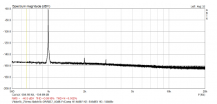
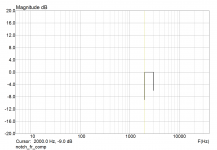
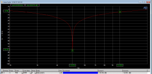
Build up a 5KHz twin-tee on one of LKA's PCB. Attached the freq response.
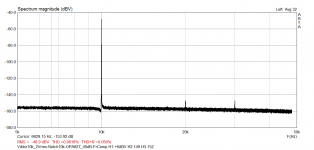
Also measured Vicnic's 5kHz oscillator with the 5kHz twin-tee in the line to the AP. The 2nd is invisible below the noise floor, the 3rd just peaks out at -144.5dBr, 1V out.
Vic is this what is expected?
Jan
Also measured Vicnic's 5kHz oscillator with the 5kHz twin-tee in the line to the AP. The 2nd is invisible below the noise floor, the 3rd just peaks out at -144.5dBr, 1V out.
Vic is this what is expected?
Jan
Attachments
Jan, do you try the osc. in the balanced mode?Build up a 5KHz twin-tee on one of LKA's PCB. Attached the freq response.
Also measured Vicnic's 5kHz oscillator with the 5kHz twin-tee in the line to the AP. The 2nd is invisible below the noise floor, the 3rd just peaks out at -144.5dBr, 1V out.
Vic is this what is expected?
Jan
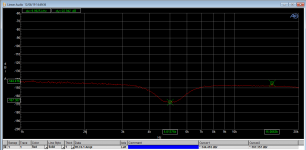
I found my measurements of your 5kHz board (second needs +4dB).
Maximum output. Probably the measurements was done on each output separately:
https://content26-foto.inbox.lv/albums/v/viccc/JanD/5kHz2.jpg
https://content26-foto.inbox.lv/albums/v/viccc/JanD/5kHz2A.jpg
No, the second graph probably is averaged.Jan, do you try the osc. in the balanced mode?
I found my measurements of your 5kHz board (second needs +4dB).
Maximum output. Probably the measurements was done on each output separately:
https://content26-foto.inbox.lv/albums/v/viccc/JanD/5kHz2.jpg
https://content26-foto.inbox.lv/albums/v/viccc/JanD/5kHz2A.jpg
- Home
- Design & Build
- Equipment & Tools
- Low-distortion Audio-range Oscillator