I have relocated equipement, 50Hz(-90dB) and high H problems remain the same.
Victor osc. is in box and poverd over SilentSwitcher on powerbank, but the same is with batt. power.
Test with 339A osc. shows 50Hz on -130dB and 2H on-135dB - -140dB and more level.
I have only those two osc.
Two problems a evident:
1. Power Harmonics
2. Harmonics from osc.istelf

Victor osc. is in box and poverd over SilentSwitcher on powerbank, but the same is with batt. power.
Test with 339A osc. shows 50Hz on -130dB and 2H on-135dB - -140dB and more level.
I have only those two osc.
Two problems a evident:
1. Power Harmonics
2. Harmonics from osc.istelf
I have relocated equipement, 50Hz(-90dB) and high H problems remain the same.
Victor osc. is in box and poverd over SilentSwitcher on powerbank, but the same is with batt. power.
Test with 339A osc. shows 50Hz on -130dB and 2H on-135dB - -140dB and more level.
I have only those two osc.
Two problems a evident:
1. Power Harmonics
2. Harmonics from osc.istelf
Connect the victor LDO in balanced mode, as I remember RTX with none balanced issues.
Hp
Here is an exaple of one of my old spectrums, 10 kHz original Victor's osc, unbalance cable of cause (1.5 or 2.0 meters of RG58 or RG59 coaxial, I don't remember exact type, about 6 mm diameter), battery powered, aluminium 1.5 mm case:
That's about -126dBc below fundamental. I think the Viktor can do better - mine does.
Jan
The high power noise is an issue. Check the line voltage. It could be high which can cause a multitude of problems. There could also be possible high harmonics from other stuff of the power line.
Sometime chancing down issues like these will unearth the cause of the distortion.
A good selftest on the RTX uses for loopback with the signal around -15dBFS on both DAC and ADC. I get virtually no power noise and best thd.
Sometime chancing down issues like these will unearth the cause of the distortion.
A good selftest on the RTX uses for loopback with the signal around -15dBFS on both DAC and ADC. I get virtually no power noise and best thd.
Probably you are working near the residual harmonic level of your ADC. It is very hard to get proper results in this situation.
You got best results when you run 0,266V signal from the oscillator. You can make a simple metal film resistors divider with the same output impedance as the oscillator has. Needs to remember, that the output impedance of the oscillator is also the part of the divider. The resistors for 1:10 divider would be 5,4kohm and 667ohm. Then you can adjust the oscillator to the max output and measure the distortions via the divider. If the result will be the same, then the distortions not came from the oscillator in your other measurements with higher levels signals.
Of course, a twin T notch also is the great tool for to get the truth.
Here are the plots of my 1kHz Victor osc.
Only by 266mV output is max THD (-132,4) achived.
By 1V or 2V THD is significulti higher (-123.4 and 117.8),
second harmonic is to high.
Anny clue why is that so?
Powerd is by Silentswitcher,the same is with batteries.
Osc. is measured direct on RTX6001
https://www.diyaudio.com/forums/att...rtion-audio-range-oscillator-victor-266mv-png
https://www.diyaudio.com/forums/att...stortion-audio-range-oscillator-victor-1v-png
https://www.diyaudio.com/forums/att...stortion-audio-range-oscillator-victor-2v-png
- it definitely can - it was just an example of 50-Hz noise.That's about -126dBc below fundamental. I think the Viktor can do better
Here are the new measurements.
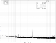
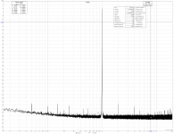
1. RTX in loopback, as Demian have proposed:
RTX has 3,16V input range and signals are -15dBFS and -10dBFS.
My RTX presented better results with -10dBFS signal, difference is about 3dB
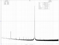
-15dBFS THD -127,1dB 2H -128,4dB
-10dBFS THD -130,2db 2H -132,6dB
https://www.diyaudio.com/forums/attachment.php?attachmentid=796500&stc=1&d=1574333821
https://www.diyaudio.com/forums/attachment.php?attachmentid=796501&stc=1&d=1574333821
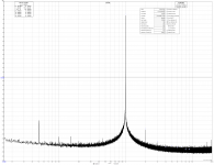
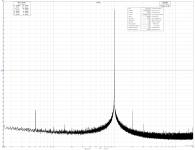
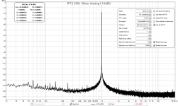
At the same time have measured Victors osc. with same signal levels and same RTX settings.
The result with -15dBFS signal was only 1dB better than RTX osc.
With -10dBFS signal result was 7-9dB worse!
-15dBFS THD -128,6dB 2H -129dB
-10dBFS THD -123,6db 2H -123,7dB
https://www.diyaudio.com/forums/attachment.php?attachmentid=796506&stc=1&d=1574335830
https://www.diyaudio.com/forums/attachment.php?attachmentid=796504&stc=1&d=1574335830
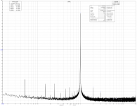
2. On Victors proposal I have made ATT and measured osc. on full power:
The results have deteriorated for about 5dB from measurements I made before, with 266mV signal from same osc.
Victor 266mV THD -132,4dB 2H -135,8dB
Victor full pow.+ATT THD -128dB 2H -131,5dB
https://www.diyaudio.com/forums/attachment.php?attachmentid=796502&stc=1&d=1574334745
Member cwtim01 has presented how should look like Victor osc. on RTX6001
(in GB for RTX6001 Audio Analyzer with AK5394A and AK4490, tread 646)
His Victor osc. have sowed THD of over -135dB(0,000017%), and 2H of over -137dB(0,000013%)!
In mine previous measurements of 339A osc. I have showed that my RTX6001 is also capable for 2H measurements of well under -140dB
From all that measured, I think that something is wrong with my exemplar of Victors osc., and that is absolutely no doubt in proper RTX functioning.
What interferences concerned - is any reason not to use power line EMI/RFI filter on RTX6001 mains power input (instead of now used simply power input connector without any filtering)?
1. RTX in loopback, as Demian have proposed:
RTX has 3,16V input range and signals are -15dBFS and -10dBFS.
My RTX presented better results with -10dBFS signal, difference is about 3dB
-15dBFS THD -127,1dB 2H -128,4dB
-10dBFS THD -130,2db 2H -132,6dB
https://www.diyaudio.com/forums/attachment.php?attachmentid=796500&stc=1&d=1574333821
https://www.diyaudio.com/forums/attachment.php?attachmentid=796501&stc=1&d=1574333821
At the same time have measured Victors osc. with same signal levels and same RTX settings.
The result with -15dBFS signal was only 1dB better than RTX osc.
With -10dBFS signal result was 7-9dB worse!
-15dBFS THD -128,6dB 2H -129dB
-10dBFS THD -123,6db 2H -123,7dB
https://www.diyaudio.com/forums/attachment.php?attachmentid=796506&stc=1&d=1574335830
https://www.diyaudio.com/forums/attachment.php?attachmentid=796504&stc=1&d=1574335830
2. On Victors proposal I have made ATT and measured osc. on full power:
The results have deteriorated for about 5dB from measurements I made before, with 266mV signal from same osc.
Victor 266mV THD -132,4dB 2H -135,8dB
Victor full pow.+ATT THD -128dB 2H -131,5dB
https://www.diyaudio.com/forums/attachment.php?attachmentid=796502&stc=1&d=1574334745
Member cwtim01 has presented how should look like Victor osc. on RTX6001
(in GB for RTX6001 Audio Analyzer with AK5394A and AK4490, tread 646)
https://www.diyaudio.com/forums/attachment.php?attachmentid=796522&stc=1&d=1574339025BTW, attached is a measurement of a single-ended Viktor 1k oscillator using the RTX. The Viktor is crippled with a 30V smps (battery based DC-DC converter) when it needs 35-36V, so it's not giving it's full performance but the limiting factor here is the ADC I believe. (When pairing with a Hall notch filter with 4x9V battery, my Viktor was verified to have an H2 of <-150dB before).
Attached Thumbnails
His Victor osc. have sowed THD of over -135dB(0,000017%), and 2H of over -137dB(0,000013%)!
In mine previous measurements of 339A osc. I have showed that my RTX6001 is also capable for 2H measurements of well under -140dB
From all that measured, I think that something is wrong with my exemplar of Victors osc., and that is absolutely no doubt in proper RTX functioning.
What interferences concerned - is any reason not to use power line EMI/RFI filter on RTX6001 mains power input (instead of now used simply power input connector without any filtering)?
Attachments
-
 RTX -15dBFS on 3,16V input.png192.6 KB · Views: 272
 -
 RTX -10dBFS on 3,16V input.png187.7 KB · Views: 274
 -
 Victor -15dBFS on 3,16V input.png184.7 KB · Views: 274
 -
 Victor -10dBFS on 3,16V input.png188.8 KB · Views: 272
 -
 Victor max out with ATT.png181.7 KB · Views: 264
 -
 cwtim01 Vistor osc on RTX6001.png89.4 KB · Views: 86
Last edited:
The Viktor is crippled with a 30V smps (battery based DC-DC converter) when it needs 35-36V, so it's not giving it's full performance
This is only trough with the original setup with the shunt regs on the Viktor board. The oscillator itself needs about +/-15 so if you bypass those shunts and directly feed +/-15V you get the advertised performance. That is what I do with the SilentSwitcher.
Jan
This is only trough with the original setup with the shunt regs on the Viktor board. The oscillator itself needs about +/-15 so if you bypass those shunts and directly feed +/-15V you get the advertised performance. That is what I do with the SilentSwitcher.
Jan
I have also made the power that way.
I see in these graphs:Victor 266mV THD -132,4dB 2H -135,8dB
Victor full pow.+ATT THD -128dB 2H -131,5dB
266mV measurement -11,5dBFs
max out measurement -21,9dBFs
Needs to made these measurements with the same dBFs level for to get the correct data.
RTX6001 Analyzer Residual THD: @1 kHz: typical -125 dB, so you are working at the residual harmonics level. These harmonics and the signal source harmonics may "play" with each other and the results may be curious. In my opinion, you need to make the signal lower when the residual harmonics became invisible and never exceed this dBFS level in further measurements. Then you can use the notch filter for to go deeper.
Victor, thanks for your comments.
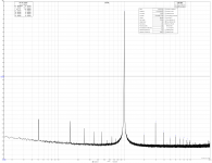
Now is measured on 1V input range and signal is -11dBFS.
(it is not -10dBFS signal because those are the best resistors I could found,
but it is close more than enough)
THD is -129,2 and 2H -130,2, so worse than 226mV measurements.
https://www.diyaudio.com/forums/attachment.php?attachmentid=796754&stc=1&d=1574418276
With RTX own osc. or with 339A osc. that is not the case.
It simply can't be that analyzer those two others osc. measure so well and than so one issue only with your osc.
Unfortunately, I haven't any dedicated noch filter, so I have feed exactly the same signal (your osc. at max. level+ATT) into 339A analyzer and look at monitor out.
https://www.diyaudio.com/forums/attachment.php?attachmentid=796762&stc=1&d=1574422753
On diagram, 0 is -80dB and second Harmonics is on -50dB so 2H is on -130db level, exactly how is RTX analyzer measured before!
Does it mean that also 339A analyzer "play" with each other residual harmonics?
It would bi interesting to hear you comment on cwtim01 measurements.
Hi has on RTX-10V input measured (BTW without any notch), and achieved over 7dB better THD and 2H then my measurement on the same range.
Does he have some special RTX analyzer without any "play" ?
Just a reminder of measurement capability of RTX analyzer:
339A 1V signal, 2H measured on -142dB!
https://www.diyaudio.com/forums/attachment.php?attachmentid=796764&stc=1&d=1574422322
Now is measured on 1V input range and signal is -11dBFS.
(it is not -10dBFS signal because those are the best resistors I could found,
but it is close more than enough)
THD is -129,2 and 2H -130,2, so worse than 226mV measurements.
https://www.diyaudio.com/forums/attachment.php?attachmentid=796754&stc=1&d=1574418276
It is interesting that particularly only this osc. "play" with each other residual harmonics!RTX6001 Analyzer Residual THD: @1 kHz: typical -125 dB, so you are working at the residual harmonics level. These harmonics and the signal source harmonics may "play" with each other and the results may be curious. In my opinion, you need to make the signal lower when the residual harmonics became invisible and never exceed this dBFS level in further measurements. Then you can use the notch filter for to go deeper.
With RTX own osc. or with 339A osc. that is not the case.
It simply can't be that analyzer those two others osc. measure so well and than so one issue only with your osc.
Unfortunately, I haven't any dedicated noch filter, so I have feed exactly the same signal (your osc. at max. level+ATT) into 339A analyzer and look at monitor out.
https://www.diyaudio.com/forums/attachment.php?attachmentid=796762&stc=1&d=1574422753
On diagram, 0 is -80dB and second Harmonics is on -50dB so 2H is on -130db level, exactly how is RTX analyzer measured before!
Does it mean that also 339A analyzer "play" with each other residual harmonics?
It would bi interesting to hear you comment on cwtim01 measurements.
Hi has on RTX-10V input measured (BTW without any notch), and achieved over 7dB better THD and 2H then my measurement on the same range.
Does he have some special RTX analyzer without any "play" ?
Just a reminder of measurement capability of RTX analyzer:
339A 1V signal, 2H measured on -142dB!
https://www.diyaudio.com/forums/attachment.php?attachmentid=796764&stc=1&d=1574422322
Attachments
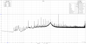
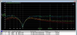
Gents, I have been playing with a setup using a composite opamp as designed by Groner and Polak. Today I got the following results:
The red curve is the measurement as inverting amp with 6dB noise gain.
Oscillator is the Vicnic which is specified as better than -150dB.
Then I increased the noise gain to 24dB, that gives the yellow curve.
It is hard to see but the distortion doesn't change so we are still measuring the basic distortion of the oscillator at around -160dB.
The third curve, the cyan one, is with 40dB noise gain. The distortion is just a dB or so higher now, at around -130dB.
My conclusion is that this is the point where the G/P starts to contribute distortion, at -170dB.
There may also be some reinforcement/cancellation involved but I don't know how to check that.
What do you think of my method, is my reasoning correct?
Jan
Attachments
Last edited:
Do that mean that you subtract a 40dB(because of 40dB gain) from cyan curve and that whole shows actual signal levels?
It sounds resonable to me.
Yes, the stage is a gain of 1 inverting stage that has been modified for 40dB noise gain. So the distortion of that stage is also increased by 40dB artificially, so to speak. So if it shows -130dB and I remove the 40dB noise gain the distortion should be -170dB.
Jan
Jan, you technique looks reasonable to me. Impressive! I wonder what non-inverting distortion would look like.
I note that the noise floor is comparable to the distortion harmonics, so there's some inherent uncertainty. Maybe more bins or more averaging might help lower the floor.
Great work.
I note that the noise floor is comparable to the distortion harmonics, so there's some inherent uncertainty. Maybe more bins or more averaging might help lower the floor.
Great work.
If you wish, you can send your board to me for testing and repairing. The results will be published in this thread. If you wish any other solution, please PM.It is interesting that particularly only this osc. "play" with each other residual harmonics!
Thanks Victor that will be great.
I have nothing against that you publish result here.
Please don't get me wrong wen i said "your osc." simply i will to find out what is going on, also in case that i was wrong, will find the right way to understand all about that and how to measure on right way.
.I have nothing against that you publish result here.
Please don't get me wrong wen i said "your osc." simply i will to find out what is going on, also in case that i was wrong, will find the right way to understand all about that and how to measure on right way.
Jan, you technique looks reasonable to me. Impressive! I wonder what non-inverting distortion would look like.
I note that the noise floor is comparable to the distortion harmonics, so there's some inherent uncertainty. Maybe more bins or more averaging might help lower the floor.
Great work.
I'm pretty sure that a non-inverting config would have quite a lot more distortion, due to non-linear input capacitance. At these levels, every electron counts!
This was FFT with flat-top window, 32 averages, 32k samples. Yes, the noise floor is almost comparable to the harmonics here, but you can still see them reliably.
Jan
Jan, to push the envelope can you connect a soundcard to the notch monitor out from the AP and use Diana to look at just the harmonics? Edmund has a routine for correcting for the insertion loss of the notch. Diana can separate the harmonics and even reconstruct the phase accurate error.
- Home
- Design & Build
- Equipment & Tools
- Low-distortion Audio-range Oscillator