research and disaster
They don’t call it the bleeding edge for nothin’.
They don’t call it the bleeding edge for nothin’.
What is most disastrous in my work is the research and divert phenomenon, where I 'invent' something and being brought off track, to divert up to a point of no return
 and then drop the whole thing. Sorry, this is OT.
How does it look 1kHz signal derived from 10MHz GPS.
Well, here is the answer:
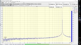
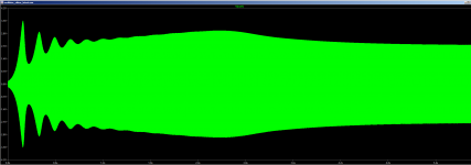
first picture presented a change in frequency of 1kHz over time

and second is a histogram of same 1kHz signal

Signal vary less than 260u(micro)Hz, and whole frequency span is only 500uHz wide.
Signal shows exceptional spectral purity and stability.
Even more fascinating is histogram of 10Hz signal derived from same 10mHz GPS:

Note the frequency span of only 50n(nano)Hz and freq.variation is not more than 27nHz!
I apologize for those whose are not interested in this matter ,but i am just fascinated with measurements.
Well, here is the answer:
first picture presented a change in frequency of 1kHz over time
and second is a histogram of same 1kHz signal
Signal vary less than 260u(micro)Hz, and whole frequency span is only 500uHz wide.
Signal shows exceptional spectral purity and stability.
Even more fascinating is histogram of 10Hz signal derived from same 10mHz GPS:
Note the frequency span of only 50n(nano)Hz and freq.variation is not more than 27nHz!
I apologize for those whose are not interested in this matter ,but i am just fascinated with measurements.
Last edited:
Actually in a sense frequency and amplitude changes are distortions. An RC network will not have enough Q to get the really narrow spectrum that a crystal oscillator can. However I'm not sure a tuning fork crystal would have the necessary Q either at 1 KHz.
I explored injection locking an oscillator but when I got it to lock the distortion shot up. The best approach might be what Boonton did with a PLL loop going into a tuning analog multiplier on the state variable. It works well but the analog multipliers are a limitation in overall performance. Still I get very good frequency stabilization and .01Hz resolution and accuracy with .0006% THD+N.
I explored injection locking an oscillator but when I got it to lock the distortion shot up. The best approach might be what Boonton did with a PLL loop going into a tuning analog multiplier on the state variable. It works well but the analog multipliers are a limitation in overall performance. Still I get very good frequency stabilization and .01Hz resolution and accuracy with .0006% THD+N.
Hi folks,
I also found that Viktor's osc drifts a small amount after warming up. I think that this, in turn, affects distortion measurements when using ARTA on the spectrum analyser function..
When using Viktor's LDO as the frequency source for the DUT, you have to switch off ARTA as a source. ARTA does not lock on to the fundamental so you still have to tell it what the source frequency is so that it can make measurements of the fundamental and any harmonics. Any difference between the LDO and what ARTA thinks is the input frequency gives incorrect results, usually lower distortion figures.
So, you have to wait for the LDO to warm up and become 'stationary' and stable. which is not a problem as I have found this takes about 10 minutes or so, and then plug the LDO directly into ARTA and adjust ARTA's generator frequency (with it switched off) untill you get a maximum reading of the fundamental using the curser line.
Once you have done this initialisation, it is not a problem, but something to be aware of.
I would also think that this situation is similar to using other tools that do not have a lock on the fundamental such as REW and RTA, but don't have any experience of these
Cheers,
Mike
Last edited:
There may be a simple solution to this. I assume that ARTA does/can measure the input frequency? It would then be a simple thing to pass that value to the FFT process. (I can do that on the AP, where I can select 'freq counter' as the notch frequency).
Maybe something to ask ARTA's author who is a member here.
Jan
Maybe something to ask ARTA's author who is a member here.
Jan
There may be a simple solution to this. I assume that ARTA does/can measure the input frequency? It would then be a simple thing to pass that value to the FFT process. (I can do that on the AP, where I can select 'freq counter' as the notch frequency).
Maybe something to ask ARTA's author who is a member here.
Jan
Hi Jan,
That sounds like a good way to check it. Never tried measuring the frequency with ARTA, but it sound like something it should be able to do - I'll give it a go later today and report back.
The important point though is to let Viktor's LDO stabilise before making very low distortion measurements (depending upon your case etc)
I think this is acceptable if you consider that some equipment has oven-encapsulated crystals etc. to ensure frequency stability
I don't know if Ivo Marteljan is a member here.
Cheers
Mike
I don't know if Ivo Marteljan is a member here.
Cheers
Mike
Hi,
He (iMat) certainly is. Dedicated ARTA thread here.
Hi Jan,
That sounds like a good way to check it. Never tried measuring the frequency with ARTA, but it sound like something it should be able to do - I'll give it a go later today and report back.
The important point though is to let Viktor's LDO stabilise before making very low distortion measurements (depending upon your case etc)
I think this is acceptable if you consider that some equipment has oven-encapsulated crystals etc. to ensure frequency stability
I don't know if Ivo Marteljan is a member here.
Cheers
Mike
BTW, it is also possible that the small frequency drift with warmup is in part due to the op amps warming up, since their gain and phase shift may change a bit as they get hotter, and the frequency of a Wein bridge oscillator can be affected slightly by phase shift in the op amps.
Heat from the op amps could also be a factor in some passive component drift if those components are in close proximity to the op amps.
Cheers,
Bob
You measure 10 kHz signal - it is close enough to your sound card hi-frequency limit, where there is much noise.Viktor's oscillator
Why are SNR and THD + N so large?
Try to measure at your sound card maximum frequency, it has to be at least 96 or 192 kHz.
Yeah, ain't it great?Point taken.
But I'm not about to wander through 740 pages of comments discussing the Holy Grail Oscillator.
I merely pointed out the one I use which more than suffices for a technician's purposes, and right away got hit with questions regarding specifications.
Oh, you just found the short one. Look for the Low-Distortion Oscillator thread,
that one has thousands of posts...better to reference post# as pages can be manually changed by the User.
By the way, that Holy Grail Oscillator was hand made in a wooden cup
wouldn't you know with gold foil shielding. It's been found and lost
for a while now. Perhaps it will turn up again some where.
Cheers,
Frequency measurement
If ARTA can't do this, use DiAna and enable the 'external sync' option.
Cheers, E
There may be a simple solution to this. I assume that ARTA does/can measure the input frequency? It would then be a simple thing to pass that value to the FFT process. (I can do that on the AP, where I can select 'freq counter' as the notch frequency).
Maybe something to ask ARTA's author who is a member here.
Jan
If ARTA can't do this, use DiAna and enable the 'external sync' option.
Cheers, E
If ARTA can't do this, use DiAna and enable the 'external sync' option.
Cheers, E
Thanks Edmond
I haven't used DiAna, maybe its time to give it a try. Where is a reputable place to download it?
Haven't been down to the workshop yet to try out this with ARTA, but sent Ivo a question via his web site. - I've helping my son paint his new apartment.
Cheers
Mike
Last edited:
- Home
- Design & Build
- Equipment & Tools
- Low-distortion Audio-range Oscillator