I'm looking forward to it.
I've been playing with this oscillator for a while, and here is the list of changes made so far:
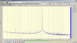
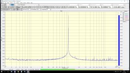
For illustration, I'm enclosing a spectrum obtained at the output voltage of 1Vrms, but please note that this is not the best result I've got - I'm not at home right now and the measurement with the lowest THD was made with another laptop. While the 2nd is the same in that plot (-130dB), the 3rd is at the level of -140dB in the lowest THD spectrum I measured.
- The two 5532s replaced by 4562, TL071 by OPA627
- The 0.047uF polyester caps in the SVO replaced by two matched 0.033uF Wima FKP2
- The 3K3 resistors replaced by 5K/0.1% glass-encapsulated resistors. I don't know their origin but I know they were used in the precision strain gauge amplifiers made by a company I used to work for.
- Removed the two 100R freq. adj. trimmers, the frequency is now adjusted by trimming R1
- Added a 22K pot in front of D1/R12 for adjusting the output voltage
- The FET is now MMBF4091 with the parallel resistor R4 reduced to 500R
- R3 in the local NFB from the 1st integrator to the inverter is reduced from 147K to 133K
The measurements were made with a MOTU Audio Express interface using the SpectrumLab S/W, the sampling rate was 48kHz, FFT length 512K, spectral window was -196dB FlatTop, and the number of FFT averages was 32.
Other artifacts in the spectrum are not due to the oscillator - they come from the SMPS powering the audio interface.
Hope this spares some time in modifying the oscillator.
Regards,
Braca
Hello Braca,
If you're still here.
Added a 22K pot in front of D1/R12 for adjusting the output voltage
Could you explain more on this?
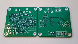
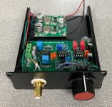
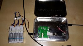
I tried to insert the VR at two places (blue rounds in picture) without success.
Only increase R12 seem to work to decrease output level.
Sincerely,
Attachments
steff1777: I've only now seen your post. As BSST pointed out, this was the change I made to the oscillator in order to get variable output voltage. For lack of time, I haven't been active on this project since then, but hope to take it up again next month. I now have a better measurement setup, so the first action would be to re-measure the performance, and then decide how to proceed. At the moment, my guess is that the oscillator needs a better rectifier than only the two diodes it uses now.
I wish you success with your experiments.
Regards, Braca
I wish you success with your experiments.
Regards, Braca
Hi all,
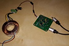
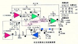
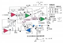
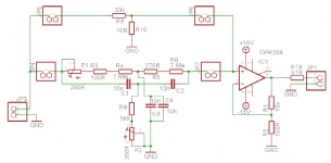
i want to build Victor oscillator according to this schematic:

Can i change the mmbf 4391 to something else, i have 2sk170bl, bf862, 2sk246 in hand. I see a 10uf capacitor in the feedback loop of ic 2a, does it need to be audiophile type or i can just use normal aluminum capacitor. Can i use 1n5819 insead of BAS70?
There are a lot of resistors have star marking, what does it mean?
Thanks!
i want to build Victor oscillator according to this schematic:
Can i change the mmbf 4391 to something else, i have 2sk170bl, bf862, 2sk246 in hand. I see a 10uf capacitor in the feedback loop of ic 2a, does it need to be audiophile type or i can just use normal aluminum capacitor. Can i use 1n5819 insead of BAS70?
There are a lot of resistors have star marking, what does it mean?
Thanks!
Given what Victor charges its hard to justify building one, unless you want to learn how hard that is to do. there is a lot of selection and hand matching necessary to get the performance he gets. They have improved as he has had more experience, which is further testament to the challenge. Its one of the places where the "audiophile" story of care in parts selection and testing makes a real quantifiable difference, unlike most audio products.
new cheap design and my new record THD")
Congrat!
new cheap design and my new record THD
Very nice ADC. What chip is used?
Anyway is unknown from where the distortions come... Probably you need the notch.
The notch is ok. Well known janascard schematic. Needs to tune the frequency. One nuance is that the schematic has no DC grounding resistor in the notch mode. You can use as example 1Mohm between the opamp pos. input and the GND. All the resistors must be metal film. The capacitors must be Wima FKP2 polypropylenes or better polystyrenes.
I am using OPA627 as the buffer amp.
I am using OPA627 as the buffer amp.
Last edited:


Hello Jan and Miklos,
The 35V supply feeds the requirements. Other question is, how clean is that supply. But this can typically affects to the noise floor, not to harmonics.
Please tell me what is your measurement tool? Are you sure that the performance is limited by the oscillator? In most cases the measurement tools are the limit. Also please, are you observing the harmonics at -100dB level or it is THD or THD+N?
Unfortunately I do not know the statistics about the performance degradation after time. One very old board that I have works ok. I know from my customers that sometimes LM4562/LME49720 becomes noisy.
The main symptoms for the oscillator normal working are:
1) onboard supply +/-15V,
2) max output level without load around 2.7V RMS,
3) typical frequency precision is not worst than +/-0,5% after warm up in room conditions,
4) sine voltage across the AGC FET regulator (source-drain) 30...40mV p-p (must be measured by low capacitance oscilloscope probe between the board's GND and the FET s/d pin),
5) sine voltage at the FET gate must be half of source-drain sine.
If you wish, I can offer to send me the boards for testing and repairing. Also if your boards are very old, I can make the possible improvements for them. Otherwise any questions please.
Victor
Hello Victor, I have a pair of your oscillators (1kHz, 5kHz). After a long delay I fired them up today, but the performance is not good, barely make -100dB.
To start at the start, is there a specific requirement for the power supply? Mine is a 317-based 35V supply.
Jan
- Home
- Design & Build
- Equipment & Tools
- Low-distortion Audio-range Oscillator