For very low level signals gold will work better than silver in a typical relay. Silver will need more current or contact force to make a good connection. The gold will actually weld at much lower levels. I think Coto published some stuff on this and a bunch of bits were sacrificed on the Blowtorch thread on this issue.
For low level signals mercury wetted relays are very good but have issues. The usual preference are relays with a wiping action on the contacts, which are a crossbar type of contact. There are some inexpensive latching relays of this type I'm told.
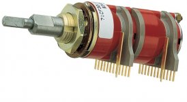
The insides of the Shibasoku represent a full proper relay implementation (and retirement options for the relay salesman) http://www.diyaudio.com/forums/equi...n-audio-range-oscillator-181.html#post3393204
For low level signals mercury wetted relays are very good but have issues. The usual preference are relays with a wiping action on the contacts, which are a crossbar type of contact. There are some inexpensive latching relays of this type I'm told.
The insides of the Shibasoku represent a full proper relay implementation (and retirement options for the relay salesman) http://www.diyaudio.com/forums/equi...n-audio-range-oscillator-181.html#post3393204
Hi Jan,
There is a chapter in my book that covers this. It is chapter 13, section 11, "fuse, relay and connector distortion". It has distortion measurements of this type made on several relays as a function of frequency.
Cheers,
Bob
Thanks Bob, I will review that section carefully.
Jan
Here is a Grayhill similar to the Uni switch. Sells for 40USD. don't know anything about it just came across it.
These are the 71 series switches.
These are good switches, I've used then to switch low level stuff in the thermal transient test bed.
Jan
Here is a Grayhill similar to the Uni switch. Sells for 40USD.
Thanks, these look fine and even better that Jan has tried them.
With options for economical, medium and top-end, that lets me feel confident that there will be no availability problems on a crucial part.
So it looks like a direct PCB mount switch, no wires and it will simplify SMT NP0 capacitors.
Now I can move towards a finalized board.
I plan to fit it on a Eurocard, anyone have any pros or cons for that?
Best wishes
David
Last edited:
RE Eurocard-
Overall I like the idea but it begs a few questions; I/O connection locations, controls and power connections. I would like both on the connector and on the front interface as options. Also what length?
Eurocard stuff is less common in the US. Finding case options will be important.
Overall I like the idea but it begs a few questions; I/O connection locations, controls and power connections. I would like both on the connector and on the front interface as options. Also what length?
Eurocard stuff is less common in the US. Finding case options will be important.
RE Eurocard-
...I/O connection locations, controls and power connections. I would like both on the connector and on the front interface as options...
Personally I plan to make it a sub-rack module, like the Elma, Vero KM6 or Schroff.
Schroff looks the most reasonably priced so far but, as usual, any recommendations welcomed.
So the output, XLR very likely, and controls on the front panel.
Power via the connector at the back, from a power supply in the back of the rack, kind of a Eurocard version of the Tektronix TM500 system.
If anyone else wants to build it then they can box it as they wish, just use the Eurocard as a plain PCB.Eurocard stuff is less common in the US.
It should fit on the smallest standard card, 160 mm deep and still have spare space.
So I will probably fit a square wave option.
The last time I did that I used a 555 because it was simple, very cheap and fairly useful.
I am sure there are better options now, anyone have recommendations?
I am inclined to take it to a separate output, maybe BNC.
Best wishes
David
A separate square output would be good for external equipment sync
I am not sure how practical it is to have the square wave run and still provide a super low distortion sine wave, there will be power supply noise and feed thru problems.
These can be overcome of course but is it worth the effort, when do I need a synchronized square wave?
I had the idea to have the square wave mainly so I can do distortion tests and then check square wave response all with one piece of equipment.
Since the square wave does not have to be super low distortion it is easy to make it heavy duty to drive 50 ohm loads.
And that seems natural to connect to a BNC.
It may be more useful to make the quadrature output available for sync, a la Cordell distortion analyser.
Best wishes
David
...Edit - The 5534 is analysed...https://books.google.com/books?id=W...IHDAA#v=onepage&q=5534 all npn output&f=false
The reference reminded me of a question.
On p.156 he states that examples use NPN bipolar but P channel MOS because the P channels have a better back gate connection, to the source rather than the substrate.
This surprises me because I would expect the N channel to be preferable due to better speed and presumably the fabrication process could be done a complementary way so it's the N channels with the better connection.
So, is this not done simply because of some established practice in the fabrication process?
Or is there a reason, to better match the P and N devices perhaps?
Best wishes
David
AP SYS-2722 and R&S UPV comparison (in japanese language)
"http://fixerhpa.blog.fc2.com/blog-entry-318.html"
what a luxury
"http://fixerhpa.blog.fc2.com/blog-entry-318.html"
what a luxury
AP SYS-2722 and R&S UPV comparison (in japanese language)
"http://fixerhpa.blog.fc2.com/blog-entry-318.html"
what a luxury
This comparison is not quite apples-to-apples, and can be misleading.
The writer did not state the option list for either machine and it is pretty clear from his findings that the UPV being tested either did not have the Low Distortion Generator (Option B1) installed or it was turned off during the tests. The SYS-2722 comes standard with a Low Distortion Generator.
If I am reading his findings right through Google Translate, a 2Vrms signal at 1kHz yielded:
SYS-2722
THD 0.00007%
THD+N 0.00016%
UPV
THD 0.00013%
THD+N 0.002%
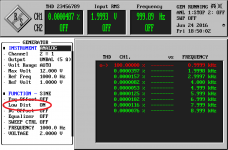
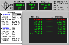
Attached are my readings from a UPL with Option B1 installed and turned on. The UPL and UPV are stated to have identical analog performance. Generator output is connected via an actual RG316 50 Ohm cable to Analyzer input.
THD 0.0000487%
THD+N 0.0002535%
It can be seen that the UPL equipped with the Low Distortion Generator Option is a stunning performer, especially when compared to the SYS-2722. In one more picture, only H3579 are shown and it was at 0.000018%!
Attachments
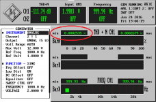
Can you redo those with the harmonics in dB? When the levels are so low the zeros are ovewhelming and dB are more manageable. The results are exceptional.
Sent from my LG-V496 using Tapatalk
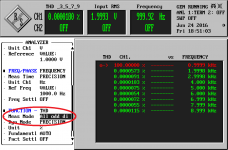
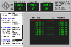
Here are the plots in dB - THD with all harmonics H2 through H9, the only odd harmonics H3 through H9.
Attachments


We just don't see those up here. One of these and their FM stereo generators would make life so much easier.
What is the real noise floor of the VP7722A Richard?
-Chris
Tones of Shibasoku FM generators floating around for cheap.
We just don't see those up here. One of these and their FM stereo generators would make life so much easier.
What is the real noise floor of the VP7722A Richard?
-Chris
I dont know -- damn low is my guess. I havent measured it yet.
But here is the combo THD+N using the internal generator + analyzer with 600 Ohm source Z:

THx-RNMarsh
- Home
- Design & Build
- Equipment & Tools
- Low-distortion Audio-range Oscillator