Grounding the two chassis together cleans up one problem and creates another at the same time. The spectrum measuring off the notch filter fills with hash.
I' not sure how to approach this problem. Batteries anyone?
The 339a oscillator and analyzer are isolated from earth ground and the outer chassis is earth grounded. Anything that connected to the 339a that is earth grounded drives the analyzer nuts raising the noise and probably causes oscillations.
One big isolation transformer to power all our test equipment including our computer would solve the problem.
A laptop would help since it doesn't require earth grounding.
Cheers,
Last edited:
1. use an individual isolation/filter on each piece of equipment..... keeps equip to equip isolated from RFI. Put ferrite cores on ac power cords. And, float ac grounds. That's what I am doing.
2. The new replacement, wide-band opamps may be oscillating. Get a o'scope to look at output, power supply, etc?? Also look at the QA400 for oscillations on and from it.
I'm not having those problems here.
2. The new replacement, wide-band opamps may be oscillating. Get a o'scope to look at output, power supply, etc?? Also look at the QA400 for oscillations on and from it.
I'm not having those problems here.
Last edited:
Rick, your results are just terrific, and I will do these things when 339A time rolls around for me. I will patiently wait for David to roll up his mods with a list of changes, then do it all at once. Thanks to you both for leading the way on this. David, I very much like the idea of swapping the order of the X100 amp and the filters -- I don't think the THD of the filters will affect the measurements.
I had written off HP's Bridged-T circuit because the clone of it I put into my old 334 gave me the same strong 2nd and 3rd H spurs as I found in the 339, and I used good new parts in the clone. Now I have to rethink this whole experience.
For meter readout, my money is still on an auto-tuned active Twin-T -- basically an HP 4333 with opamps and first-class parts. If you don't know that analyzer -- it was the bridge between the 334 and the 339 -- the manual is available on line, maybe at Agilent or one of the other sources of free books. I can't remember now where I got it.
1. use an individual isolation/filter on each piece of equipment..... keeps equip to equip isolated from RFI. Put ferrite cores on ac power cords. And, float ac grounds. That's what I am doing.
2. The new replacement, wide-band opamps may be oscillating. Get a o'scope to look at output, power supply, etc?? Also look at the QA400 for oscillations on and from it.
I'm not having those problems here.
Floating the grounds will do it and that explains the absents of any ground problems.
There is still the issue of the earth ground via USB on the QA400.
Just for me try connecting something that is not ground floating and see if you get the same. Dick says he doesn't have these problems. My 339 maybe faulty.
Cheers,
David:
Your QA400 is connected to a PC of some sort. That PC is in turn connected to power (unless its a laptop on battery). Whenever I use anything like that near low noise circuitry the leakage from the switching supplies around the loop(s) becomes the dominant noise. If there is a speaker or headphones its usually audible. I end up running the laptop on batteries in those conditions.
I have a 7L5 (and other similar tools) but no HP339 (and I do have 9 other distortion analyzers, just never added one of those). If someone near me wants to explore I would be happy to see what is happening.
Filter distortion- on my Boonton's the high pass filter kicks up the 2nd harmonic a lot when its engaged. I have tried the usual tricks with no success. I need to try the wonder opamp to see if it helps. The AD797 made no change. I think it may be a common mode issue. I believe the signal is at 1V at that stage. In the Boonton the filter is in front of the notch filter so its especially sensitive to the added distortion. is that a potential issue in the HP339?
Attachments
1. use an individual isolation/filter on each piece of equipment..... keeps equip to equip isolated from RFI. Put ferrite cores on ac power cords. And, float ac grounds. That's what I am doing.
2. The new replacement, wide-band opamps may be oscillating. Get a o'scope to look at output, power supply, etc?? Also look at the QA400 for oscillations on and from it.
I'm not having those problems here.
These problems existed before any component changes. Nothing new from the mods.
Ill try floating the scope ground.
David:
Your QA400 is connected to a PC of some sort. That PC is in turn connected to power (unless its a laptop on battery). Whenever I use anything like that near low noise circuitry the leakage from the switching supplies around the loop(s) becomes the dominant noise. If there is a speaker or headphones its usually audible. I end up running the laptop on batteries in those conditions.
I have a 7L5 (and other similar tools) but no HP339 (and I do have 9 other distortion analyzers, just never added one of those). If someone near me wants to explore I would be happy to see what is happening.
Filter distortion- on my Boonton's the high pass filter kicks up the 2nd harmonic a lot when its engaged. I have tried the usual tricks with no success. I need to try the wonder opamp to see if it helps. The AD797 made no change. I think it may be a common mode issue. I believe the signal is at 1V at that stage. In the Boonton the filter is in front of the notch filter so its especially sensitive to the added distortion. is that a potential issue in the HP339?
Hi Demian,
The filters in the 339 are just before the x100 amplifier which feeds the meter's RMS convertor. This is far downstream from the notch filter. All the signals in the 339a are attenuated to 10mV and then amplified with a gain of 100 post filtering and normalized to 1Vrms FS for the meter.
Taking the signal from the output of the notch filter doesn't exhibit any of the mentioned problems. These only effect the meter and monitor output.
Cheers,
I have had some success just sticking a suitable resistor in series with the spectrum analyzer input. Something between 1K and 10K soldered to the center conductor on the "business end" of a short piece of coax, with about 1/2" of hookup wire connecting the coax shield to the signal ground point closest to where I wanted to measure. The free end of the resistor is your measurement "probe", though for best results I'd tack-solder it to the point I'm measuring.. . . I also have access to an RF spectrum analyzer at work but it is 50 or 75 ohm input Z. That's a hard load for what we have. . . .
The attenuation is pretty fierce, but spectrum analyzers can get down to the microvolt (or less) range if you know how to set up the bandwidths and sweep rates.
Yeah, this destroys the spectrum analyzer's amplitude calibration but you can still see frequencies, sideband structure, etc. And you can still do relative, before-and-after kinds of measurements to determine whether some change improves, or degrades, the signal you're looking at and by roughly how much.
It also helps protect the spectrum analyzer input from DC voltages, since the typical RF instrument is rather intolerant of DC at its input.
Several incarnations ago this technique helped me track down the source, and the injection mechanism, of some troublesome noise on power supply lines. (This was before half the 'scopes on the market had built-in FFT features, though I don't know if that would have helped since I was looking in the HF/VHF range.)
Dale
I would make a small coil of maybe 10-20 turns on a 1/2" to 1" former as a pickup. Couple it directly into the 50 Ohm cable (the mismatch won't matter). If there is something in distress it will radiate and the coil will pick it up. You could sniff all around the box to find the unhappy parts and no electrical connection to make a mess of things. Also good for getting depressed about power supply radiation and how its nearly impossible to eliminate.
You can buy these coils but they are way expensive.
You can buy these coils but they are way expensive.
I'm using active probe with 50 Ohm output impedance, then
high-pass filter to remove audio, then
preamplifier, if required, then
spectrum analyzer or scope
high-pass filter to remove audio, then
preamplifier, if required, then
spectrum analyzer or scope
I would make a small coil of maybe 10-20 turns on a 1/2" to 1" former as a pickup. Couple it directly into the 50 Ohm cable (the mismatch won't matter). If there is something in distress it will radiate and the coil will pick it up. You could sniff all around the box to find the unhappy parts and no electrical connection to make a mess of things. Also good for getting depressed about power supply radiation and how its nearly impossible to eliminate.
You can buy these coils but they are way expensive.
Great idea Demian. It just gave me another. Remember those balun transformers the ones used for 75 ohm cable to FM receivers and very old TV's. 75 ohm to 300 ohm. We still have a bunch of those at work. DC won't pass through them and it's a lot closer to 600 ohms than 75. It also offer some input protection to the analyzer. We have inline 75 ohm attenuators at work as well. I can slip these in on the 75 ohm side. The input sensitivity is 0dBV - 1mV into 75 ohms for cable systems. 60 dB of padding is not a problem. This will give me 9KHz to 1 GHz.
Thanks,
Last edited:
Noise spectrum
I must go into the test equipment rental business --
I have here three analyzers which can be used (covering 20Hz to 6.6GHz); I put one on the 339A which covers 150Kz to 1Ghz and just connected the output (339A output 'off') directly into the spectrum analyzer input. Looked up and down.. out to 100MHz and stopped... didnt see anything but random noise. Did same next with an HP3400 and just measured the rms noise level.... which is fairly high by conventional terms. However, low enough to be useful for FFT to below the THd of the oscillator. BUT... I did notice that the input is super sensitive to picking up just a hand wave near the input port. This can indicate a high input Z. The schematic doesnt indicate such. However, the input does have an inductor in series right at the input terminal. That could do it. Going to investigate this more.... input Z/sensitivity. Thx-RNMarsh
The input Z is supposed to be 100K.
There is something wrong with my 339a. This is a repair.
I can't continue with mods with a problem like this going on. Anything I do maybe meaningless.
It could be something simple like a poor ground somewhere. It's very likely a ground trace burned open at or near the input or monitor output. It's used gear after all and I have no idea of what it's been through.
Fortunately, I did repair work for many years. I just don't like having to repair my own stuff.
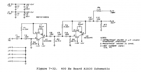
did you notice the oscillator common is not the same common as the analyzer? Grnd 1 and grnd 2. Where did you ground the coax from the osc to the front panel bnc?
I haven't connected the BNC yet. It's just an intention.
Yes I know they are different grounds. The BNC should be connected to analyzer gnd I think.
We have enough interconnections it easy to isolate each section.
With the notch filter disconnected the meter goes to zero and is not effected by the monitor ground being connected to an external ground. The problem seems to be at or before the notch filter. I'm betting on input damage.
With notch filter diconnected
This is interesting.
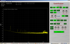
With the notch filter disconnected the meter, in distortion mode, rests at 0.0016% with the sensitivity set at -80dB FS and all filter in. There is not distortion signal at this point. Therefore this is all noise from the distortion amplifier, the auto set level, the filters and meter amplifier. The noise floor measures about -90dBV on the QA400. Or is it noise?
The oscillator is still running at -10dBV. When the oscillator range switch is switched to the off position the meter drops to a zero reading. So how is the oscillator signal getting to the remaining circuits? the path is disconnected. If there is a another path this explains why the meter never really drops to the distortion and noise levels we measure by other means.
Cheers,
David.
This is interesting.
With the notch filter disconnected the meter, in distortion mode, rests at 0.0016% with the sensitivity set at -80dB FS and all filter in. There is not distortion signal at this point. Therefore this is all noise from the distortion amplifier, the auto set level, the filters and meter amplifier. The noise floor measures about -90dBV on the QA400. Or is it noise?
The oscillator is still running at -10dBV. When the oscillator range switch is switched to the off position the meter drops to a zero reading. So how is the oscillator signal getting to the remaining circuits? the path is disconnected. If there is a another path this explains why the meter never really drops to the distortion and noise levels we measure by other means.
Cheers,
David.
- Home
- Design & Build
- Equipment & Tools
- Low-distortion Audio-range Oscillator