I've been testing my speakers with a very hastily put together stand which didn't have any facility for rotating the speaker to do off axis measurements.
Yesterday I had the day off and decided to make myself a new speaker testing stand with a swivelling top. (Skip to the end if you just want to see the pictures") )
)
I wasn't sure how I was going to do it so I headed off to the hardware store to get something to use as the swivel. I was thinking Lazy Susan (the thing that goes in the middle of the table and spins around) but they didn't have a mechanism.
I sort of explained to the guy what I wanted and he sent me to where the castors (swivelling wheels) were. I found a reasonably heavy duty one for around $4.50 and bought it (having no idea how I was going to use it.
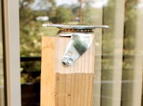
I got home and took off the wheel and realised it would be just about the right size to fit over the end of a piece of wood I had lying around. So I got out the router and trimmed back the end about 8mm and it was a nice snug fit. I had another scrap bit of wood that could be used as a cross piece for the bottom.
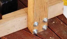
I went back to the hardware shop and got 4 X 4" 5/16 bolts 4 X 1.5" 5/16 bolts 8 X nuts and 8 X washers. (about $6.00)
I used the existing test platform (which was actually originally the caul for applying the veneer to the top and bottom of my boxes) drilled some holes Routed out the platform (very roughly!) and bolted the whole thing together.
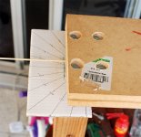
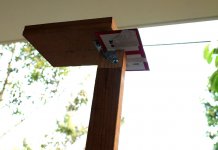
As I wanted to make taking off axis measurements easy and accurate I got a piece of cardboard and marked it with lines at 15 degree increments. There is a small gap at the front of the castor and I cut the cardboard so that it can slot under it.
Needing an indicator for the angle, I drilled a small hole in the middle of the front of the platform and inserted a wooden skewer (pointy end in the hole is smaller that the diameter of the skewer). I adjusted the cardboard until the skewer was exactly in line when in the on axis and also in the 90 deg off axis positions.
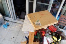
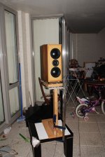
This stand is really only suitable for smaller speakers but I'm sure could be scaled up for bigger ones (provided a heavy enough duty castor was purchased . It is rick solid with my MTM's
The stand is simply clamped to a suitable platform (in this case the coffee table from the living room). a more elaborate base could be made, but this worked well for me
The only slight issue is that the platform is not quite level sloping back a very slight amount (so my vertical is probably off by 1 or 2 degrees). It would have been a good idea to use a spirit level when initially placing the castor for determining where to drill the hole for the locating bolt.
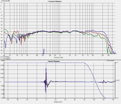
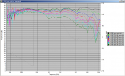
Anyway I'm very pleased I made it. It made doing off axis measurements so easy! The front of the platform is about an inch in front of the axis of rotation which will introduce a very small error off axis (slightly longer time of flight) but this I don't think is significant (you can see the effect in the holm impulse response below on the orange impulse). The last picture is the FR of the MTM at 15 deg increments through 90 deg, the post wouldn't have been complete without the results The gauge using the skewer was so simple and effective, literally only took seconds to get the next angle, well worth the effort!
Anyway here are some pictures as they will tell the story better than all of the verbiage above
Tony.
Yesterday I had the day off and decided to make myself a new speaker testing stand with a swivelling top. (Skip to the end if you just want to see the pictures
) I wasn't sure how I was going to do it so I headed off to the hardware store to get something to use as the swivel. I was thinking Lazy Susan (the thing that goes in the middle of the table and spins around) but they didn't have a mechanism.
I sort of explained to the guy what I wanted and he sent me to where the castors (swivelling wheels) were. I found a reasonably heavy duty one for around $4.50 and bought it (having no idea how I was going to use it.
I got home and took off the wheel and realised it would be just about the right size to fit over the end of a piece of wood I had lying around. So I got out the router and trimmed back the end about 8mm and it was a nice snug fit. I had another scrap bit of wood that could be used as a cross piece for the bottom.
I went back to the hardware shop and got 4 X 4" 5/16 bolts 4 X 1.5" 5/16 bolts 8 X nuts and 8 X washers. (about $6.00)
I used the existing test platform (which was actually originally the caul for applying the veneer to the top and bottom of my boxes) drilled some holes Routed out the platform (very roughly!) and bolted the whole thing together.
As I wanted to make taking off axis measurements easy and accurate I got a piece of cardboard and marked it with lines at 15 degree increments. There is a small gap at the front of the castor and I cut the cardboard so that it can slot under it.
Needing an indicator for the angle, I drilled a small hole in the middle of the front of the platform and inserted a wooden skewer (pointy end in the hole is smaller that the diameter of the skewer). I adjusted the cardboard until the skewer was exactly in line when in the on axis and also in the 90 deg off axis positions.
This stand is really only suitable for smaller speakers but I'm sure could be scaled up for bigger ones (provided a heavy enough duty castor was purchased . It is rick solid with my MTM's
The stand is simply clamped to a suitable platform (in this case the coffee table from the living room). a more elaborate base could be made, but this worked well for me
The only slight issue is that the platform is not quite level sloping back a very slight amount (so my vertical is probably off by 1 or 2 degrees). It would have been a good idea to use a spirit level when initially placing the castor for determining where to drill the hole for the locating bolt.
Anyway I'm very pleased I made it. It made doing off axis measurements so easy! The front of the platform is about an inch in front of the axis of rotation which will introduce a very small error off axis (slightly longer time of flight) but this I don't think is significant (you can see the effect in the holm impulse response below on the orange impulse). The last picture is the FR of the MTM at 15 deg increments through 90 deg, the post wouldn't have been complete without the results
The gauge using the skewer was so simple and effective, literally only took seconds to get the next angle, well worth the effort! Anyway here are some pictures as they will tell the story better than all of the verbiage above
Tony.
Attachments
-
 castor.jpg129.2 KB · Views: 440
 -
 junction..jpg101.3 KB · Views: 425
 -
 guage_detail.jpg114.9 KB · Views: 419
 -
 DSC_9541.jpg88.9 KB · Views: 416
 -
 DSC_9542.jpg66 KB · Views: 412
 -
 DSC_9544.jpg101.8 KB · Views: 269
 -
 new_crossover_1.27M_with_15_and_30_off_axis.png73.6 KB · Views: 255
 -
 horizontal_polar.png45.1 KB · Views: 169
Last edited:

I don't like the bearing in that design because its not stable and its not necessary. Just use two (say 24" x 24") 3/4" melamine coated (one side) boards. I actually have the top board a little smaller than the bottom one so I can mark the angles on the lower one. Place the melamine sides together and use some grease between them. Put a pin in the center (I used a 3/4" piece of brass). This combination is very stable at loads even > 100 lbs. The rotation is "stiff" but easily doable.
Any vibration in the bearing will be a problem in the data.
One more thing. I have found the ideal angular spacing to be nonlinear. I use 0, 5, 10, 15, 20, 30, 40, 50, 60, 80, 100, 120, 150, 180
One needs the greatest resolution where there is the great change and that is always about the forward axis. Taking data equally spaced is a waste of time because at angles > 60 almost nothing at any siginificant level is changing. For dipoles this might be different is the rear radiation was of interest.
Last edited:
I actually made mine to rotate on the floor on a 2' by 4' piece of plywood and some furniture gliders made of teflon. I can make it rotate as tight or as loose as I want. I also put 'lazy susan' bearings in the swivel part rated for 400#s I think. The front of my speaker(s) match the center of the bearing. For bookshelf measurements I have some stands made for studio monitors with adjustable height to get the longest reflection free impulse possible under whatever circumstance.
Nice job Tony! And I like the speakers!
Dan
Nice job Tony! And I like the speakers!
Dan
Thanks Pano and Dan teflon sliders is another great idea.
Earl I didn't think about possible vibrations in the bearing (it was a rather spur of the moment design). Could be more of a problem if you scaled it up for bigger speakers I guess.
As it is with the weight distribution on the platform being uneven front to back the bearing is not really free to move about. I suspect that if it were bad enough to be contributing to the measurement that more attention would need to be paid to damping of the speaker under test
I did think about using two pieces of MDF (the melamine is a good idea!) with a pivot pin, but as one of my "requirements" was to get the pivot point as close to the front of the platform as possible. I was unsure I could do it and maintain stability with the platform at 90deg, the castor works very well in this regard..
I'll try the angles you mention next time thanks for the tip!
Tony.
teflon sliders is another great idea. Earl I didn't think about possible vibrations in the bearing (it was a rather spur of the moment design). Could be more of a problem if you scaled it up for bigger speakers I guess.
As it is with the weight distribution on the platform being uneven front to back the bearing is not really free to move about. I suspect that if it were bad enough to be contributing to the measurement that more attention would need to be paid to damping of the speaker under test
I did think about using two pieces of MDF (the melamine is a good idea!) with a pivot pin, but as one of my "requirements" was to get the pivot point as close to the front of the platform as possible. I was unsure I could do it and maintain stability with the platform at 90deg, the castor works very well in this regard..
I'll try the angles you mention next time thanks for the tip!
Tony.
- Status
- This old topic is closed. If you want to reopen this topic, contact a moderator using the "Report Post" button.