ZXTN2018FTA, it has the marking "851" on the sot-23, so I'd guess
that it is the same chip inside.
< Transistoren - Bipolar (BJT) - Einzeln | Diskrete Halbleiterprodukte | DigiKey >
that it is the same chip inside.
< Transistoren - Bipolar (BJT) - Einzeln | Diskrete Halbleiterprodukte | DigiKey >
No need to shield ?
How much is the input bias current ?
Not better than SQRT(2*Ic/Beta*q)
13pA/rtHz for the datasheet beta of 100, meaning that a 5 ohm source resistor will swamp the voltage noise.
The lost beauty of the low noise bipolars (Hitachi, Rohm) was the unique combination of very low rbb with a very high beta. My stash of 2SC2546 and 2SA1084 have betas over 800.
Otherwise, there are lots of power devices with low rbb.
The last time I measured Beta of a ZTX851 it came out 250.
Good for you
 . That's over the typical value in the datasheet (200). 2SC2546 has 250 min and 1200 max. They are polysilicon emitter devices, and according to Kleinpenning https://pure.tue.nl/ws/files/1376103/Metis122824.pdf that's as good as you can get from a noise (1/f, GR, RTS) perspective. Unfortunately I'm not aware of any discrete transistors built in such a process today (not that I'm surprised, though).
Last edited:
I read that Infineon BFP640 is also at 300 pV/rtHz. 40 GHz Ft can be handled with a 22 Ohm
ferrite bead in the base. It probably has a high 1/f corner, that would not be a
show stopper in my case of a chopper unless it is excessive. Early voltage is HUGE, (kV)
so it would make an effective cascode. hfe is 110-270, not impressive.
But then there is the BFP840, SIGe:C, with hfe > 400 at small currents.
Ouch, Ft = 80 GHz. Ferrite is your friend. Maybe I should get some samples.
€ 0.40 @ 1 is cheap.
Last edited:
70 nV/rtHz
This number is [not] impressive.
This number is [not] impressive.
Ooohps, 70 pV/rtHz. What is a factor of 1000 among friends?
I read that Infineon BFP640 is also at 300 pV/rtHz. 40 GHz Ft can be handled with a 22 Ohm
ferrite bead in the base. It probably has a high 1/f corner, that would not be a
show stopper in my case of a chopper unless it is excessive. Early voltage is HUGE, (kV)
so it would make an effective cascode. hfe is 110-270, not impressive.
But then there is the BFP840, SIGe:C, with hfe > 400 at small currents.
Ouch, Ft = 80 GHz. Ferrite is your friend. Maybe I should get some samples.
€ 0.40 @ 1 is cheap.
I doubt they will deliver 0.3nV/rtHz at low frequencies. That's what SiGe and III-V compounds devices are not famous for (they will certainly have significant amounts of GR noise).
What is the purpose of C2 & R6 in Scott's schematic in the first post?
Thanks.
So the op-amps just follow the collector voltage on the FET at DC and act like an inverting op-amp a AC. This way the optical bias loop sets a stable output DC voltage without a huge cap in series with the 1 Ohm resistor as you would need if you simply used an op-amp and a supply splitter. The optical bias also conveniently makes a negative voltage for the FET gate so this works on a single supply.
Am I correct in thinking that at DC, or anything below 0.08Hz, the first opamp acts as a follower, and the optical loop controls the dc operating point of the FET. Anything higher than 0.08Hz, you introduce gain such that global feedback fixes the overall gain at 1000?
I am curious how you chose the RC values for 0.08Hz. I suppose it depends on the response time of the PV devices?
I have a stash of mocd207 that I hope to adapt for this purpose, so any insights you can offer is greatly appreciated.
Thanks!
I am curious how you chose the RC values for 0.08Hz. I suppose it depends on the response time of the PV devices?
I have a stash of mocd207 that I hope to adapt for this purpose, so any insights you can offer is greatly appreciated.
Thanks!
Am I correct in thinking that at DC, or anything below 0.08Hz, the first opamp acts as a follower, and the optical loop controls the dc operating point of the FET. Anything higher than 0.08Hz, you introduce gain such that global feedback fixes the overall gain at 1000?
I am curious how you chose the RC values for 0.08Hz. I suppose it depends on the response time of the PV devices?
I have a stash of mocd207 that I hope to adapt for this purpose, so any insights you can offer is greatly appreciated.
Thanks!
Yes, there is the issue of multiple low frequency poles and peaking at some very low frequency. I built it to check the performance but yes the details usually escape the casual user.
The big difference between the PV arrays and the optically connected transistors is the ability to generate a large voltage outside of the rails. You only need a volt or so so you might be able to stack two to get all you need. IIRC the transistors are only able to generate -.6V or so each.
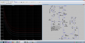
I have made a new amplifier based on FETs. With the standard architecture I had continuously stability problems. That is: common source FET, cascode, active or passive load, opamp for loopgain and feedback via divider into the source, which makes the FET no more common source at all.
Somewhat frustrated I simulated some other published amplifiers that claimed to be stable, but plotting real part of (Zin = input voltage/input current) revealed negative input impedance around 100 KHz. Tinkering with gate inductors and ferrite beads just moved the unstable region around but it did not remove it.
Remember that if it does not oscillate in a certain setup, that does not mean it is stable.
I found no way short of slowing everything down or killing the low noise property. But I want 1 MHz BW at least and no noise, as far as it gets.
I sacrificed the feedback. The signals to be measured are very small, so distortion is not a problem. But now evertyhing is temperature dependent and I cannot use an active load because the gain then is not well-defined. ---> less gain, less PSSR.
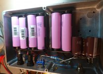
Now I have a fixed load resistor. PSSR is less of a problem since I use Lithium batteries anyway and 4 cells deliver +16V, just so enough for enough gain. Nevertheless, 10 Ohms
and 20000 uF reduce the injected noise from the battery a little bit.
For fixed gain, I need to keep the drain current constant. I do that with a simple current mirror. It is heavily degenerated with many VTs. That brings the next ugly thing: the source must be decoupled for low frequencies, too. High frequencies are cheap.
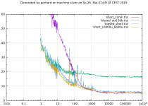
DC at the source is only a few 100 mV. I used 3 pcs. 4700uF / 2V6 in addition to the RF stuff. That was BAD. Digikey 493-4582-1-nd Nichicon.
It brought the purple measurement: 1/f corner at 800 Hz, rise 30 dB/decade. That's not 1/f !!11!! And it is not in the simulation. It took some work to exclude the possible causes one by one.
Using 5*3300uF/10V for the source and 2*3300uF for the reference current decoupling healed that. (Rubycon 105° probably not organic polymer). I can reconfigure the amplifier with jumpers to -650mV to the gate and GND to the source. That really helped debugging.
The result is 250-300 pV/rt Hz for 1 IF3602 pair at 29 mA.
Not breathtaking, 300pV is typ. for a single transistor at 5 mA according to the "data sheet".
Probably I'll use only 1 FET; this amplifier is intended for 2 channels and cross correlation.
That's easier in the end.
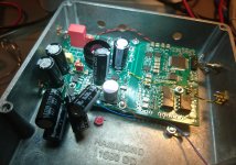
Alternatively I could use up to 16 BF862 or similar, but will test that on the next board revision only. I have a LT3094 to stabilize the Vee because that sets the drain current.
The decal was 25% too small. Soldering that was an adventure with this thermal pad in the middle.
Gain vs. temperature is about 0.8 dB for 10°C. If that turns out to annoy, I'll stabilize the temperature at 35°C. The Controller for that is done already, at least in Spice.
short_12mF = input shorted, source = 3*4700uF 2V5 (purple)
biased_att12dB = gate bias -666mV, source at GND, a 12 dB attenuator with the other side open looks like 60 Ohm, i.e. 1nV/rt Hz thermal.
biased_short = gate bias -666mV, input ac-shorted
short_16000u_6600u = 5*3300uF at the source, 2*3300uF for bias string
I have no idea where this rise just above 10, 100 and 100 Hz comes from. Maybe a programming error of mine.
Does anyone know how to model the noisy leakage of the electrolytics?
Wet tantalum 4700u/25 was not better than the 10V ALU.
Somewhat frustrated I simulated some other published amplifiers that claimed to be stable, but plotting real part of (Zin = input voltage/input current) revealed negative input impedance around 100 KHz. Tinkering with gate inductors and ferrite beads just moved the unstable region around but it did not remove it.
Remember that if it does not oscillate in a certain setup, that does not mean it is stable.
I found no way short of slowing everything down or killing the low noise property. But I want 1 MHz BW at least and no noise, as far as it gets.
I sacrificed the feedback. The signals to be measured are very small, so distortion is not a problem. But now evertyhing is temperature dependent and I cannot use an active load because the gain then is not well-defined. ---> less gain, less PSSR.
Now I have a fixed load resistor. PSSR is less of a problem since I use Lithium batteries anyway and 4 cells deliver +16V, just so enough for enough gain. Nevertheless, 10 Ohms
and 20000 uF reduce the injected noise from the battery a little bit.
For fixed gain, I need to keep the drain current constant. I do that with a simple current mirror. It is heavily degenerated with many VTs. That brings the next ugly thing: the source must be decoupled for low frequencies, too. High frequencies are cheap.
DC at the source is only a few 100 mV. I used 3 pcs. 4700uF / 2V6 in addition to the RF stuff. That was BAD. Digikey 493-4582-1-nd Nichicon.
It brought the purple measurement: 1/f corner at 800 Hz, rise 30 dB/decade. That's not 1/f !!11!! And it is not in the simulation. It took some work to exclude the possible causes one by one.
Using 5*3300uF/10V for the source and 2*3300uF for the reference current decoupling healed that. (Rubycon 105° probably not organic polymer). I can reconfigure the amplifier with jumpers to -650mV to the gate and GND to the source. That really helped debugging.
The result is 250-300 pV/rt Hz for 1 IF3602 pair at 29 mA.
Not breathtaking, 300pV is typ. for a single transistor at 5 mA according to the "data sheet".
Probably I'll use only 1 FET; this amplifier is intended for 2 channels and cross correlation.
That's easier in the end.
Alternatively I could use up to 16 BF862 or similar, but will test that on the next board revision only. I have a LT3094 to stabilize the Vee because that sets the drain current.
The decal was 25% too small. Soldering that was an adventure with this thermal pad in the middle.
Gain vs. temperature is about 0.8 dB for 10°C. If that turns out to annoy, I'll stabilize the temperature at 35°C. The Controller for that is done already, at least in Spice.
short_12mF = input shorted, source = 3*4700uF 2V5 (purple)
biased_att12dB = gate bias -666mV, source at GND, a 12 dB attenuator with the other side open looks like 60 Ohm, i.e. 1nV/rt Hz thermal.
biased_short = gate bias -666mV, input ac-shorted
short_16000u_6600u = 5*3300uF at the source, 2*3300uF for bias string
I have no idea where this rise just above 10, 100 and 100 Hz comes from. Maybe a programming error of mine.
Does anyone know how to model the noisy leakage of the electrolytics?
Wet tantalum 4700u/25 was not better than the 10V ALU.
Attachments
Last edited:
Gain vs. temperature is about 0.8 dB for 10°C. If that turns out to annoy, I'll stabilize the temperature at 35°C. The Controller for that is done already, at least in Spice.
I remember a circuit of a log amplifier with a transistor array using some of the transistors maintain heat stability. Here you have more moving parts.
I was happy to see the HP41CX on your computer desktop.
Care to share your IF3601 model? (OOPS, found it)
Last edited:
I think I found that model somewhere here on diya. It has > 1A Idss,
which could happen according to the data sheet. All in all it seems
quite optimistic regarding noise, but so does the data sheet. Fred B.
some years ago in usenet sci.electronics.design made similar observations
from real devices. I have bought about 16 pairs; all they have in common
is that they are all different. Maybe us Mouser customers get the rest of the
selection. Still within the open end data sheet limits. 16 pairs is real money.
In a previous life I have made a engine controller chip that had log/antilog functions
to do Lambda probe voodoo; I had a fat BJT on it to enforce constant chip
temperature.
That new temp controller was an item in the LTspice user group recently
because I had some bug in the temperature stepping syntax.
My new source decoupling capacitors are right now floating somewhere
above the Atlantic between Louisville, KY and my doorstep, together with
very interesting RF chips. Over the weekend I'll prepare the new Gerbers
for the preamp and mail them tho PCBway in China. Then, 4 days later,
the boards will arrive here. The world is shrinking.
I also have a hp41 in my Android smart phone, Go-41 or so in the app shop.
If the smart phone lies on the table in a dark room, you can just barely tell
if it's the real thing or not.
cheers, Gerhard.
Looks like we are getting a monster thunderstorm here right now.
Last edited:
- Home
- Design & Build
- Equipment & Tools
- My version of the G = 1000 low noise measurement amp (for Ikoflexer)