Decided that in fairness to the THD, s/n thread the IG-18 should be discussed on its own.
I modified this IG-5218 a long time ago -- looks like it's in need of modding again --
I modified this IG-5218 a long time ago -- looks like it's in need of modding again --
An externally hosted image should be here but it was not working when we last tested it.
Disconnecting the Schmitt Trigger:
An externally hosted image should be here but it was not working when we last tested it.
Just for fun, I once dropped in a TO-5 version LM317 for the power supply's regulator transistor, with appropriate changes and substitutions of parts on the little PCB; works great.
The meter circuit significantly loads the output and benefits from a buffer amp; a precision meter rectifier/buffer from an opamp that mounts right on the meter terminals is one of those projects I never got around to designing...
The meter circuit significantly loads the output and benefits from a buffer amp; a precision meter rectifier/buffer from an opamp that mounts right on the meter terminals is one of those projects I never got around to designing...
I have an IG-18 (1969?) that I just finished doing most of the mods per the Williamson article. I have not done the driver transistor pair yet as I am waiting on parts. I have a pair of 2SC2235/2SA965 on order (ebay) to try.
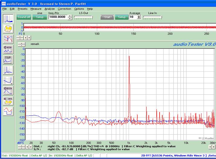
I also have an HP333A that shows almost identical distortion numbers, so I believe the plots I'm getting with AudioTester V3 thorugh my M-Audio M-192.
I get less distortion (0.008%thd) and higher harmonic/interference with the IG-18 than I do if I use the computer sound card output (M-192). This is at 1Vrms.
A LM317 may be next after the driver transistors.
The Kruger modification in The Audio Amateur 3/84 is probably the best -- the author ditches the transistor oscillator and substitutes an NE5534. The light bulb AVC is replaced with a photo-dependent resistor AND amplitude compensation is added via a new wafer on the range switch. He also provides for switching the square wave circuitry on or off. As mentioned before, the square wave circuitry adds a lot of noise.
I did a bunch of mods based on several articles, but I was never able to go below 0.01% ( HP 334A). I mounted the power transformer outside, used +/- 20 volt 317/337 regulators, used a LMEXXXXX 22 volt op amps, for the oscillator and a LME XXX for output, bypassed the output cap, output offset is near 0 volts, used switches to enable square wave and meter, meter is now buffered and with 1000uf across the meter it is basically flat from 1 hz to 110khz slow but flat, used a led for power lamp.
I made a clone of the ig18 from the audio amateur article. it has all the mods from the article plus some of my own and has given excellent service for many years now.
Distortion is very low. my home made distortion meter has a minimum reading (noise floor) of 0.0016% with the input shorted. It shows the same figure from the "IG18" so it must be considerably better than this figure!
Distortion is very low. my home made distortion meter has a minimum reading (noise floor) of 0.0016% with the input shorted. It shows the same figure from the "IG18" so it must be considerably better than this figure!
The 84 article would be about right. It has a home made opto isolator made from a jumbo led fitted into an old style IF transformer former with an LDR in the other end. I am pretty sure I didn't use any sort of buffer after the "last" op amp.... It's years since I built it and a good while since I last had the lid off. It's in use everyday though.
Just a note from a new poster here. The hum in the IG-18/SG-5218 is largely from the power transformer's magnetic radiation and can't be fixed with filtering or a better PS regulator. A nice small toroid transformer fixes the problem completely -- check the AVEL catalog.
Reg Williamson's "greening" mods in Audio Amateur, go most of the way. A bit less distortion can be had by using an N-channel JFET as an adjustable current source in place of R4 56kohm and tweaking for lowest THD. Connect the drain to the emitters of the diff. pair Q1/2, the gate to ground, and the source to ground through a 5kohm pot in rheostat connection.
Being able to turn off the Schmitt trigger square-wave generator is essential to lowest THD. For those trying to use the HP 333/334 to measure the result: don't -- the residual of the HP analyzer is only a bit less than 0.01% at 1kHz, and is largely second harmonic. I'll be trying a few simple mods to the HP 334 soon, which involve using OPA134 op-amps -- then we'll see how sensitive the phase and level detectors are in those analyzers.
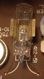
Now, a question -- what is the lamp type used for L1 in the IG-18? I no longer own one. but need to know....
Best,
Dick Moore
Reg Williamson's "greening" mods in Audio Amateur, go most of the way. A bit less distortion can be had by using an N-channel JFET as an adjustable current source in place of R4 56kohm and tweaking for lowest THD. Connect the drain to the emitters of the diff. pair Q1/2, the gate to ground, and the source to ground through a 5kohm pot in rheostat connection.
Being able to turn off the Schmitt trigger square-wave generator is essential to lowest THD. For those trying to use the HP 333/334 to measure the result: don't -- the residual of the HP analyzer is only a bit less than 0.01% at 1kHz, and is largely second harmonic. I'll be trying a few simple mods to the HP 334 soon, which involve using OPA134 op-amps -- then we'll see how sensitive the phase and level detectors are in those analyzers.
Now, a question -- what is the lamp type used for L1 in the IG-18? I no longer own one. but need to know....
Best,
Dick Moore
Now, a question -- what is the lamp type used for L1 in the IG-18? I no longer own one. but need to know....
In the instruction/assembly manual it's just "Lamp".
After a lot of searching and asking in other fora, it appears that the lamp MIGHT be a T2 wire lead type 120PS -- 120V @ 25mA, 4800 ohms hot, perhaps 500-800 ohms cold. If someone with an IG-18 or -5218 can measure the cold resistance, it would really help to pin this down. An IG-18 is on its way to me now via USPS, so more fun lies ahead with before and after results of greening.
The bridged-tee frequency selector is in the negative feedback loop and the amount of neg. feedback keeps the unit from oscillating at any frequency except for the tuned frequency. With the 10:1 ratio capacitor values Heath used -- which are both good for tuning and very practical, because caps can be shared between ranges, making for lower cost -- the attenuation of the tuned signal is about 15-16dB, making the attenuation approximately 6X at tuning center. This means that the positive feedback leg has to have an attenuation of the output signal of approximately the same amount. If you assume that Heath thought that the feedback adjust pot should operate near the middle of its range, then the ground leg of the feedback attenuator would be around 375 ohms. For 6X attenuation, the feedback leg would have to be around 1800-1900 ohms -- a very reasonable value for the 120PS lamp with some current running through it.
The bridged-tee frequency selector is in the negative feedback loop and the amount of neg. feedback keeps the unit from oscillating at any frequency except for the tuned frequency. With the 10:1 ratio capacitor values Heath used -- which are both good for tuning and very practical, because caps can be shared between ranges, making for lower cost -- the attenuation of the tuned signal is about 15-16dB, making the attenuation approximately 6X at tuning center. This means that the positive feedback leg has to have an attenuation of the output signal of approximately the same amount. If you assume that Heath thought that the feedback adjust pot should operate near the middle of its range, then the ground leg of the feedback attenuator would be around 375 ohms. For 6X attenuation, the feedback leg would have to be around 1800-1900 ohms -- a very reasonable value for the 120PS lamp with some current running through it.
- Home
- Design & Build
- Equipment & Tools
- Heath IG-18 IG-5218