That looks promising, so Jack you think that this fet could be used in Lafferty’s circuit?
Obviously, there’s a board for you too if you want one!
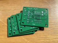
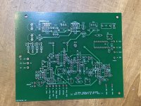
Last but not least, can you approve of the PCB I drafted for the mux switch? I think it’s finalized, and if it’s ok, then I’d send it to fab it.
Parts have already arrived from Mouser - the BOM I published earlier - so I can build a prototype.
Obviously, there’s a board for you too if you want one!
Last but not least, can you approve of the PCB I drafted for the mux switch? I think it’s finalized, and if it’s ok, then I’d send it to fab it.
Parts have already arrived from Mouser - the BOM I published earlier - so I can build a prototype.
Your layout looks good to me. There's one tiny patch of flood near the U1 and C9 reference designators that may be floating, but that's nit-picking and a non-issue.
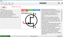
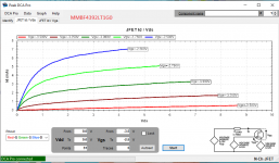
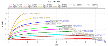
Vicktors uses the MMBF4391 in his design and has the lowest distortion oscillator that I'm aware of. I've pasted a Digikey search of devices in that family.
Blocked
Nice work!
Steve
P.S. The Digikey link shows Blocked in my post but seems to work anyway. Let me know if it doesn't link.
Vicktors uses the MMBF4391 in his design and has the lowest distortion oscillator that I'm aware of. I've pasted a Digikey search of devices in that family.
Blocked
Nice work!
Steve
P.S. The Digikey link shows Blocked in my post but seems to work anyway. Let me know if it doesn't link.
Last edited:
Ok for the floating patch, I’ll take care of it either with a via or just deleting it. Thank you!
As for Viktors oscillator, I know! I got one set at 1khz a few months back.
Lets see how it works, I’ll send the board for fab next week.
Once it gets here, I’ll have to test it, hopefully should not be too hard.
As for Viktors oscillator, I know! I got one set at 1khz a few months back.
Lets see how it works, I’ll send the board for fab next week.
Once it gets here, I’ll have to test it, hopefully should not be too hard.
Vicktors uses the MMBF4391 in his design and has the lowest distortion oscillator that I'm aware of. I've pasted a Digikey search of devices in that family.
I guess you just have to add the suffix "LT1G" and the replacement comes up. This is the OnSemi Part, the one I cited is Central Semi.
I as well have the Victor 1k and 10k == remarkable devices.
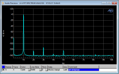
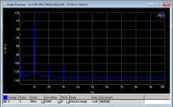
Vicktors uses the MMBF4391 in his design and has the lowest distortion oscillator that I'm aware of. .
Indeed! (Yellow is Victor's)
Attachments
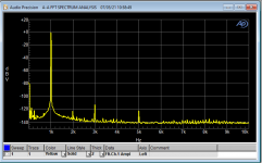
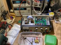
Wow you’ve got a high end Audio Precision system, I didn’t realize it was a 2722
The mux board is being made, in a week or so I should have it.
Once I stuff it I need to test it, hopefully it won’t be too hard.
Jack, can I ask if you’re drafting a complete circuit based on this design? You post every now and then a portion of something bigger ...
The mux board is being made, in a week or so I should have it.
Once I stuff it I need to test it, hopefully it won’t be too hard.
Jack, can I ask if you’re drafting a complete circuit based on this design? You post every now and then a portion of something bigger ...
Jack, can I ask if you’re drafting a complete circuit based on this design? You post every now and then a portion of something bigger .
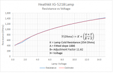
I have plenty of oscillators, but I do have the IG-5218 lying around collecting dust. It's been gomered pretty good with a hack saw to the power supply!
I don't plan anything bigger at the moment.
Board for beefier output stage -- 2.5 x 1.5 inches.
I had thought to use LME49600, but there have been some reports of it not living up to the noise spec.
Can you elaborate more? This is also quite interesting.
Can you elaborate more? This is also quite interesting.
The LME49600 is intended to be inside a feedback loop. That should reduce its noise to that of the associated opamp.
I have on my to-do list grafting an LME49600 into my KH4400 output so I can really drive 50 Ohms, maybe even to 5V (with 50 Ohms internal source, or 10V/100 Ohms).
Hi guys,
I have doubts because, in a lengthy private email exchange with Steve Lafferty in regards to mux use to switch AGC caps in his circuit, he raised very sensible and objective concerns in the actual implementation.
As a foreword, i did send him the link to this thread and the ideas suggested.
I got permission to share these concerns with you.
... how to sense position of the multiplier switch?
Adding high-value resistors (say 1Mohm) between pins 1 to 5 of the front wafers of the switch and a DC voltage (say +5V): since pin-11 is gnd, the DC voltage on the connected terminals will drop to 0. Then, DC voltages could be sensed and used to encode the two digital lines to control the mux.
However, there are practical problems:
(1) There are two wipers so two pins at a time will drop to 0.
(2) The largest cap is 5.0uF so the time constant will be 5 seconds for that one, when charging.
(3) I don't know what effect the 1Mohm resistors will have on the oscillator quality. In part, this may depend on the frequency setting.
(4) The presence of the DC might cause extended settling time, particularly when the 5uF cap is in play.
(5) Something would have to be done to keep the DC voltage out of the oscillator's amplifier (U1)--perhaps it could be AC coupled. In theory, one can operate the IG-18 with the variable Rz digit being the only non-zero value. That makes the max resistance across the top of the notch filter, 2Mohms. But that may be considered invalid operation. Discarding that case, the max would be 200Kohms--still disturbingly high compared to the 1Mohms pull-up resistors (but not necessarily a deal-killer).
Plus, there is a more fundamental problem: The IG-18 is specified to operate down to 1Hz. A lowpass filter (LPF) which substantially removes this from the logic sense signal would have to have a cutoff frequency (Fo) much lower than 1Hz. For example, an RC LPF with Fo=0.1Hz has a time constant of about 1.6 seconds. It's doubtful that would be acceptable. Also, it's not clear if the 20dB rejection provided by that filter would be adequate, so it might need to lower in frequency and therefore slower.
In light of his concerns, I decided to build a test board anyway (I already received the PCB form the fab and had also the BOM delivered from Mouser), just to see in practice what happens.
What are your ideas, comments?
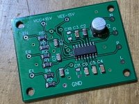
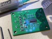
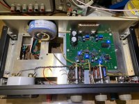
In any case, here’s my IG18 with Lafferty’s circuit built on my redraft of the PCB board, with the updated PS using LM317/337 IC’s.
Since i live in Italy, I had to replace the original transformer that had a 47+47V output with a 30VA toroidal 18+18V.
In the US, it's not needed; wiring the transformer for 240v will give out 22V, that's just great for the double IC without having to use difficult to find HVT parts.
Since i live in Italy, I had to replace the original transformer that had a 47+47V output with a 30VA toroidal 18+18V.
In the US, it's not needed; wiring the transformer for 240v will give out 22V, that's just great for the double IC without having to use difficult to find HVT parts.
Attachments
Last edited:
I really appreciate the close scrutiny. I like to find problems early when they're perhaps less painful. 
This is actually a very serendipitous feature of the range switch. The second deck wiper removes any range cap not in active play (i.e. open) from the "T" node of the Bridged-T; thus, any trash associated with the pull-up networks won't conduct into into frequency determining networks.
Only the 0.05uF and 0.005uF caps are sensed. Fortunately they are sufficient to establish the position of the range switch in all four bands.
The pull-up networks present in one of three ways: open path in range switch, grounded by the front deck, or connected to the opamp output pin which has low source impedance. If the suggested value of 330K resistors is adopted, the load presented to the opamp output is about 165K for each connected pull-up network.
Only the 0.05uF and 0.005uF caps are sensed. The time constant is 100nF and 330K, so should "feel" responsive.
I don't believe the Mux board affects these issues one way or the other.
I suggest temporarily setting the Mux board to the side and debugging the Lafferty board in the IG-18; you won't have the convenience of the range switch to manipulate the added AGC paths, but you can address those with jumper connections, band by band. Once you're happy with performance with the distortion performance on all bands, only then introduce the Mux board into operation.
To reiterate, you should establish base-line performance before adding Mux. Otherwise, if performance is disappointing, you won't know where to focus suspicion.
Great work! Good luck!
Steve
Hi guys,
I have doubts because, in a lengthy private email exchange with Steve Lafferty in regards to mux use to switch AGC caps in his circuit, he raised very sensible and objective concerns in the actual implementation.
As a foreword, i did send him the link to this thread and the ideas suggested.
I got permission to share these concerns with you.
... how to sense position of the multiplier switch?
Adding high-value resistors (say 1Mohm) between pins 1 to 5 of the front wafers of the switch and a DC voltage (say +5V): since pin-11 is gnd, the DC voltage on the connected terminals will drop to 0. Then, DC voltages could be sensed and used to encode the two digital lines to control the mux.
However, there are practical problems:
(1) There are two wipers so two pins at a time will drop to 0.
This is actually a very serendipitous feature of the range switch. The second deck wiper removes any range cap not in active play (i.e. open) from the "T" node of the Bridged-T; thus, any trash associated with the pull-up networks won't conduct into into frequency determining networks.
(2) The largest cap is 5.0uF so the time constant will be 5 seconds for that one, when charging.
Only the 0.05uF and 0.005uF caps are sensed. Fortunately they are sufficient to establish the position of the range switch in all four bands.
(3) I don't know what effect the 1Mohm resistors will have on the oscillator quality. In part, this may depend on the frequency setting.
The pull-up networks present in one of three ways: open path in range switch, grounded by the front deck, or connected to the opamp output pin which has low source impedance. If the suggested value of 330K resistors is adopted, the load presented to the opamp output is about 165K for each connected pull-up network.
(4) The presence of the DC might cause extended settling time, particularly when the 5uF cap is in play.
Only the 0.05uF and 0.005uF caps are sensed. The time constant is 100nF and 330K, so should "feel" responsive.
(5) Something would have to be done to keep the DC voltage out of the oscillator's amplifier (U1)--perhaps it could be AC coupled. In theory, one can operate the IG-18 with the variable Rz digit being the only non-zero value. That makes the max resistance across the top of the notch filter, 2Mohms. But that may be considered invalid operation. Discarding that case, the max would be 200Kohms--still disturbingly high compared to the 1Mohms pull-up resistors (but not necessarily a deal-killer).
Plus, there is a more fundamental problem: The IG-18 is specified to operate down to 1Hz. A lowpass filter (LPF) which substantially removes this from the logic sense signal would have to have a cutoff frequency (Fo) much lower than 1Hz. For example, an RC LPF with Fo=0.1Hz has a time constant of about 1.6 seconds. It's doubtful that would be acceptable. Also, it's not clear if the 20dB rejection provided by that filter would be adequate, so it might need to lower in frequency and therefore slower.
I don't believe the Mux board affects these issues one way or the other.
In light of his concerns, I decided to build a test board anyway (I already received the PCB form the fab and had also the BOM delivered from Mouser), just to see in practice what happens.
What are your ideas, comments?
I suggest temporarily setting the Mux board to the side and debugging the Lafferty board in the IG-18; you won't have the convenience of the range switch to manipulate the added AGC paths, but you can address those with jumper connections, band by band. Once you're happy with performance with the distortion performance on all bands, only then introduce the Mux board into operation.
To reiterate, you should establish base-line performance before adding Mux. Otherwise, if performance is disappointing, you won't know where to focus suspicion.
Great work! Good luck!
Steve
I suggest temporarily setting the Mux board to the side and debugging the Lafferty board in the IG-18; you won't have the convenience of the range switch to manipulate the added AGC paths, but you can address those with jumper connections, band by band. Once you're happy with performance with the distortion performance on all bands, only then introduce the Mux board into operation.
To reiterate, you should establish base-line performance before adding Mux. Otherwise, if performance is disappointing, you won't know where to focus suspicion.
Sage advice -- put your pants on one leg at a time!
- Home
- Design & Build
- Equipment & Tools
- Heath IG-18 IG-5218