Hi Jack,
I now realize I swapped the K and H terminals in my sketch compared to Heath's original assignments. So I'm responsible for creating a lot of confusion. Very sorry! For better consistency, I should have had my opamp output on H, - input on K, and the E0 and E1 taps on the opposite sides of the .05 and .005 caps.
Sorry again for the needless consternation. But I feel reassured that the scheme should work.
Thanks again,
Steve
I now realize I swapped the K and H terminals in my sketch compared to Heath's original assignments. So I'm responsible for creating a lot of confusion. Very sorry! For better consistency, I should have had my opamp output on H, - input on K, and the E0 and E1 taps on the opposite sides of the .05 and .005 caps.
Sorry again for the needless consternation.
But I feel reassured that the scheme should work.Thanks again,
Steve
Last edited:
Hi guys,
I wanted to try the mux switch by making a test board with only the circuit that both of you described, including the sensing network. I basically got nowhere. The ADG409 BRZ component is obviously not available in DipTrace. Ok, no prob lets download the 3d and symbol files from Mouser. Nope, the symbol set does not import in the SW.... Argh, it took me ages only to manage to find a compatible chip from Maxim (dg409by i think) for which the component file was available, and then it was crazy still to import it... then, I found out that there was not even a single smd component , following Jack’s schematic, that Mouser or others stock in the libraries. So lets find something with the same footprint in the available parts database in DipTrace, how hard can that be. and again only the complete part no is visible to choose each component.. a 1206 470nf 25v is hidden under 234dfred23888-(556)... or something like that. One full day in total frustration and I cannot begin to imagine what the hell the SW engineers that coded this crap ECAD though when they designed it this way.
Can you please help me to at least get the switcher and caps board going? I beg you....
Hi Pizzigri,
I sympathize with your frustration. I'm going to try to learn KiCad unless someone persuades me otherwise, but I'm still in paper design mode, not ready to begin PCB. Out of curiosity, I did check to see if any xx409 mux was in the KiCad symbol library, but no joy. (There was an '309 mux...) There are Youtube videos about creating KiCad symbols when needed. I presume there's similar support for Eagle software.
Maybe other members will comment if there's any de facto favorite CAD in the DIY community? I know FREX seems to use KiCad successfully--- which helped lead me in that direction.
Hang in there!
Noting some minor differences between the 339 manual which I have and the SL version -- R50 (2k7) has a 200pF capacitor in parallel (marked C47 with an asterisk, so perhaps optional). This was originally 510pF, but change notice #10 marked a difference.
I use Multisim and Ultiboard -- but my version is now quite long in the tooth! When National Instruments bought the software developer they increased the price 10x
I use Multisim and Ultiboard -- but my version is now quite long in the tooth! When National Instruments bought the software developer they increased the price 10x
Last edited:
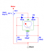
Interesting -- the output at the top of the "Y" capacitor is 90 degrees out of phase with the main output. I wonder if we could obtain a 10V pk-pk "quadrature" output without a lot of difficulty.
You're quite right about the 90 degree phase shift. I first discovered this from studying a Khron-Hite generator manual and they mention using it for quadrature output. Their arrangement swapped the position of the tuning R's and C's so that the pillar element was a resistor rather than a capacitor.
Also interesting: with resistor input, the transfer function is 2nd order lowpass; with cap, the transfer function is 2nd order high pass.
Steve
Hi guys,
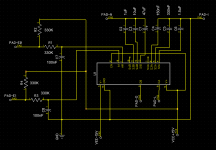
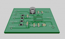
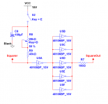
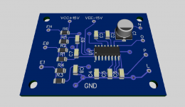
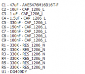
so after so much frustration in trying to learn how to use an ECAD, I managed to replicate Jacks' circuit, adding to it the hopefully correct parts and values. The MUX I could not find a 3D model for, but I found foot print and schematic. All parts are 1206, and i have checked on Mouser for a real BOM saving it in a project. The IC I used is a Maxim Integrated DG409DY, I believe it is a 1:1 replacement or so, but in any case I was more interested in the footprint and connections. Can you guys tell me if this could work? How to improve, and eventually how to test it?
Please take it as it is, an attempt by a complete noob....
Jack by any chance you are also doing a board?
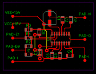
Also, GND is connected to Pad I, but would it be advisable to connect it to a ground plane or to the copper fill on both sides?
so after so much frustration in trying to learn how to use an ECAD, I managed to replicate Jacks' circuit, adding to it the hopefully correct parts and values. The MUX I could not find a 3D model for, but I found foot print and schematic. All parts are 1206, and i have checked on Mouser for a real BOM saving it in a project. The IC I used is a Maxim Integrated DG409DY, I believe it is a 1:1 replacement or so, but in any case I was more interested in the footprint and connections. Can you guys tell me if this could work? How to improve, and eventually how to test it?
Please take it as it is, an attempt by a complete noob....
Jack by any chance you are also doing a board?
Also, GND is connected to Pad I, but would it be advisable to connect it to a ground plane or to the copper fill on both sides?
Attachments
Last edited:
Pizzigri,
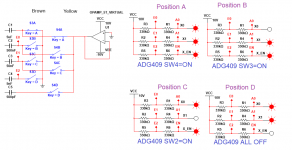
I think your PCB looks fine, but I believe the capacitor values/Ref Des need review. The selected mux channels do not present in band-sequential order--- i.e. by design, mux channel is not in binary counting order.
I quote Jack's truth table for convenience:
In general, I like ground planes.
I think your PCB looks fine, but I believe the capacitor values/Ref Des need review. The selected mux channels do not present in band-sequential order--- i.e. by design, mux channel is not in binary counting order.
I quote Jack's truth table for convenience:
I agree with the truth table.
X1 = S4 closed
X10 = S3 closed
X100 = S1 closed
X1000 = S2 closed
__________________
In general, I like ground planes.
The ENABLE must be brought low for position 4. Just another two resistors and cap.
I must have missed this. How do I implement it in the circuit and board I am trying to make?
scratch that, would you please just give me the correct values/Ref Des for C1-2-3 and C6-7-8? I would really REALLY appreciate it. I got really frustrated with the DipTrace weird interface and my head is mush right now
Last edited:
OK!
I apologize. I am only a hobbyst that during last year's lockdown started dabbling in electronics... so please have patience!
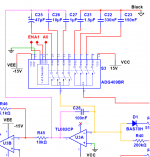
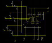
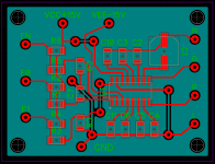
Jack, I believe everything's clear now. I've updated the schematic and added the third level shifter for EN, and rerouted everything so hopefully I've managed to have a nice board.
I apologize. I am only a hobbyst that during last year's lockdown started dabbling in electronics... so please have patience!
Jack, I believe everything's clear now. I've updated the schematic and added the third level shifter for EN, and rerouted everything so hopefully I've managed to have a nice board.
Here it is, with the updated schematic from DipTrace, and the BOM. And I finally managed to add a 3d model to the MUX. Jack, howeasy to use/good is NI Multisim and Ultiboard? DipTrace is driving crazy, although I did manage to obtain something out of it.
Attachments
Hi Pizzigri,
If you've only started to dabble in electronics, I think you're making amazing progress!
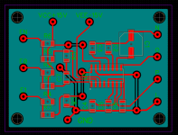
Re the layout: the clearance between C9's pad and a nearby via is tight--- easy to get a solder bridge. I assume green is solder mask, so clearance of mask to part footprints is a work in progress?
Full respect to Jack, but I don't think we yet agree on hookup of mux address lines. But if your layout could accommodate sites for added caps at mux pins 4 and 13, the layout would be flexible enough to handle either outcome.
Great progress!
Steve
If you've only started to dabble in electronics, I think you're making amazing progress!
Re the layout: the clearance between C9's pad and a nearby via is tight--- easy to get a solder bridge. I assume green is solder mask, so clearance of mask to part footprints is a work in progress?
Full respect to Jack, but I don't think we yet agree on hookup of mux address lines. But if your layout could accommodate sites for added caps at mux pins 4 and 13, the layout would be flexible enough to handle either outcome.
Great progress!
Steve
Hello Steve,
OK thank you! I corrected that glitch with the via. As for the rest, I added a 1206 pad on both pins 4 and 13, however if the electrolithic (C1) has to be moved it would make no difference... the board would have to be rerouted and refabbed.
What is not convincing you in regards to the circuit? I was under the impression that we all sorted it out?
As for the compliments, I really appreciate it! But, yes, I just started. I got the passion but there's very little behind it in terms of knowledge and studies.
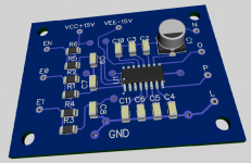
ETA: no, the green is a copper flood in the bottom layer plus bottom traces. The solder mask is blue, you can see it in the 3D pic
All my best,
Franco
OK thank you! I corrected that glitch with the via. As for the rest, I added a 1206 pad on both pins 4 and 13, however if the electrolithic (C1) has to be moved it would make no difference... the board would have to be rerouted and refabbed.
What is not convincing you in regards to the circuit? I was under the impression that we all sorted it out?
As for the compliments, I really appreciate it! But, yes, I just started. I got the passion but there's very little behind it in terms of knowledge and studies.
ETA: no, the green is a copper flood in the bottom layer plus bottom traces. The solder mask is blue, you can see it in the 3D pic
All my best,
Franco
Last edited:
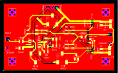
Great! Here's the updated board.
I also cleaned up the C4-5-6 traces to U1, they were weird.
I was thinking. If the switching board works, this is possibly the most up to date and completely drop-in upgrade mod for the IG-18 and 5218, in conjunction with the existing SL board (..or the one i modded, with more modern 317-337 PS).
Especially becuse there's no need to change or modify the mechanical range rotary switch... Rotary switches are gettin amazingly expensive and hard to find these days... plus, the original 2% film caps can be used (and eventually padded for accuracy) making the mod effortless, for whoever wants to do it in the future.
The best would be integrating the whole circuit in SMD making it extremely easy to implement!
Attachments
- Home
- Design & Build
- Equipment & Tools
- Heath IG-18 IG-5218