Banned
Joined 2002
For Christmas my Fiance asked me what i wanted, I asked her to get me a Uni-T Scope hand held meter, It's only 10mhz but that is all i need for audio.
I got the meter a few days ago and have been playing with it and the software, for 190$ im pretty impressed, it's not heavy at all, takes 4 AA batteries, and has a very bright and crisp clean display that is really easy to read.
the unit was purchased from mib-instrument's.
UNI-T UT81B 40MSa/s Oscilloscope digital multimeter
I can post pictures if people want to see better pictures.


Soon i will be purchasing a Function gen & 2 more desktop meter's ( witch i want )
This has been my second purchase from this good company.
I got the meter a few days ago and have been playing with it and the software, for 190$ im pretty impressed, it's not heavy at all, takes 4 AA batteries, and has a very bright and crisp clean display that is really easy to read.
the unit was purchased from mib-instrument's.
UNI-T UT81B 40MSa/s Oscilloscope digital multimeter
I can post pictures if people want to see better pictures.
Soon i will be purchasing a Function gen & 2 more desktop meter's ( witch i want )
This has been my second purchase from this good company.
UNI-T ut-81b
Got my ut-81b yesterday and am well pleased with it; it's a pity there was no 'scope probe lead but for the price (£125 inclusive) I suppose it won't kill me to spend a few more £'s on a 10 MHz probe.
A very serious omission, though, is that of a probe compensation adjustment signal output; there must be a suitable rectangular wave signal available within the 'scope's circuits and a simple buffer would add a very few pennies to the cost?
That whinge apart it's great value; providing as it does the functions of a portable 'scope cum multimeter and those of a bench 'scope when tethered to a computer - sadly only for Windows users; those of us using Linux or O S X, will have to downgrade to an inferior O S!
UT 81B
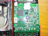
I opened mine up the day it arrived and it looked to be well built with decent quality components on a good-looking PCB - only time and use will tell tho'!!
I'll take some pics tomorrow or the day after (busy, busy!) and if I can fathom out how to attach/link them I'll gladly do so.
I opened mine up the day it arrived and it looked to be well built with decent quality components on a good-looking PCB - only time and use will tell tho'!!
I'll take some pics tomorrow or the day after (busy, busy!) and if I can fathom out how to attach/link them I'll gladly do so.

Thank you for the great shots.
They have some nice tatalums on there. Only thing I might be concerned with is its protection circuit which I can't quite see from the pictures. I do see a single glass fuse. Usually I'd prefer to see atleast a ceramic, but I guess I'm being picky.
They have some nice tatalums on there. Only thing I might be concerned with is its protection circuit which I can't quite see from the pictures. I do see a single glass fuse. Usually I'd prefer to see atleast a ceramic, but I guess I'm being picky.
No, you're not being picky and yes, you're right it is a LBC (glass) fuse, but there's no reason you can't fit a HBC one; though I must admit I'm never likely to use this instrument on mains supplies; it's more for bench use on audio systems etc. where the fault level is nowhere near that of a domestic, or industrial, supply system. For the latter one is definitely safer using pukka (certified) kit like my trusty Fluke DMM which is, after all, specifically designed to be safe on such systems having a fuse with a rupturing capacity in the kA range.
With that reservation and the application of a modicum of common sense in its use I still think it's good value and a worthy addition to my test kit - it's still a pity about the lack of a probe compensation set-up signal though!
As an after-thought, have you looked at the "dpscope"? - not a stand-alone 'scope as it needs to be tethered to a P.C. (Windows, NOT a Mac, sadly!) but great value twin-channel, pretty versatile AND it has a probe compensation output! - PDAMusician's PocketPC Music Softwaredpscope/
Hope the comments are useful; let me know what you get and what you think.
Dave.
No, you're not being picky and yes, you're right it is a LBC (glass) fuse, but there's no reason you can't fit a HBC one; though I must admit I'm never likely to use this instrument on mains supplies; it's more for bench use on audio systems etc. where the fault level is nowhere near that of a domestic, or industrial, supply system. For the latter one is definitely safer using pukka (certified) kit like my trusty Fluke DMM which is, after all, specifically designed to be safe on such systems having a fuse with a rupturing capacity in the kA range.
With that reservation and the application of a modicum of common sense in its use I still think it's good value and a worthy addition to my test kit - it's still a pity about the lack of a probe compensation set-up signal though!
As an after-thought, have you looked at the "dpscope"? - not a stand-alone 'scope as it needs to be tethered to a P.C. (Windows, NOT a Mac, sadly!) but great value twin-channel, pretty versatile AND it has a probe compensation output! - PDAMusician's PocketPC Music Softwaredpscope/
Hope the comments are useful; let me know what you get and what you think.
Dave.
No I've never heard of it but I just looked it up, and it seems decent to say the least.
Component selection looks nice. All genuine Microchip silicon, unlike the nice unmarked ones on the Uni-T . A Wima cap in there. Panasonic electrolytic and plenty of MLCCs/Tantalums.
Pretty cheap as well. I'm considering buying just the PCB and ICs for $20. Other components hopefully wouldn't cost any more than $20-30USD.
Looks nice, really....How about a protection circuit on this one? Or is it different with PC based ones. I don't really see any MOVs, PTCs, discharge tubes, current sense etc. I'm going to take a half a bet that those two cylindrical things close to the inputs are fuses. Not sure what else they've got.
But I'll consider it. Maybe I'll throw my Pentium 3 down by my bench.
Hi,
since I am the designer of the DPScope I thought I should add some answers:
As far as input protection is concerned, these posts hopefully answer your questions:
dpscope.freeforums.org • View topic - Can I damage my computer with large voltages at the scope?
and
dpscope.freeforums.org • View topic - How can I measure voltages larger than 20V?
The "two cylindrical things" are actually trimmer capacitors and are used to compensate the scope inputs so the response stays flat up to the full required bandwidth; without capacitive compensation the input stage would have a measly 60 kHz bandwidth...
I have a pretty detailed explanation of the hardware design (including the input stage) on my website:
DPScope - A Low-Cost PC-Based Oscilloscope
Feel free to ask more questions if anything is still unclear! I'm doing this as a hobby and I am always glad if people get some use out of what I design.
Regards,
Wolfgang
Re the dpscope - there, you've got the answer straight from the horse's mouth (no offence, Wolfgang!) and there's not much I can add except that if you go DIY you don't get the SMD setup that is in the ready-built one: I debated whether or not to go for DIY but am perfectly happy with the price of the ready-built unit, it is very well made (better, I think, than I could do) and for the saving you'd make, not worth the bother of DIY'ing.
Dave.
Dave.
If I have the opportunity to DIY, I do it....even if its a few dollars more.
Anyway, I didn't know the max voltage was 20V. That's okay for most things, but....honestly, I'd like something more in the range of 50V.
But I can measure up to 200V in 1:1 mode?
I'd probably only use my o-scope for things with lesser voltage anyway, and the price is very good, so it's hard to say.
- Status
- This old topic is closed. If you want to reopen this topic, contact a moderator using the "Report Post" button.
- Home
- Design & Build
- Equipment & Tools
- Review - UNI-T UT81B Scope / Meter