Hi all
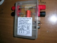
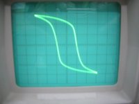
I found a bit of free time to build a very simple circuit by which the B-H curve of a transformer can be traced on the screen of a dual channel oscilloscope.
The circuit is from an old book titled “Transformer and Inductor Design Handbook” by Colonel Wm.T.McLyman (JPL).
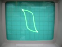
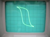
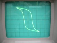
The B-H curve as traced on the scope is a mirror image (left to right) of the actual one, but this is not a big problem.
It can be used in observing the point (input voltage) of core saturation, also to compare different x-formers. (In all cases with secondary open-circuit).
The resistor values in the circuit are for primary voltage of 230V and for primary Idle current of around 50mA.
Oscilloscope should be set to 2v/div on both channels (probe X1).
Caution:
Lethal voltages present.
It is mandatory to have a safety isolation transformer to provide the voltage to the primary of the x-former under observation.
Regards
George
I found a bit of free time to build a very simple circuit by which the B-H curve of a transformer can be traced on the screen of a dual channel oscilloscope.
The circuit is from an old book titled “Transformer and Inductor Design Handbook” by Colonel Wm.T.McLyman (JPL).
The B-H curve as traced on the scope is a mirror image (left to right) of the actual one, but this is not a big problem.
It can be used in observing the point (input voltage) of core saturation, also to compare different x-formers. (In all cases with secondary open-circuit).
The resistor values in the circuit are for primary voltage of 230V and for primary Idle current of around 50mA.
Oscilloscope should be set to 2v/div on both channels (probe X1).
Caution:
Lethal voltages present.
It is mandatory to have a safety isolation transformer to provide the voltage to the primary of the x-former under observation.
Regards
George
Attachments
Hi,
I'm a physics teacher and i use nearly the same topology in my lab:
amp clamp meter in primary of transformer: I1 that is a mirror of H
H=N1.I1/L (L average length of core,N1 primary turns)
RC integrator in secondary (R=1M , C=1uF time constant=1s)
B=(1/(N2.S)).V2 (V2=output of integrator, S Cross section Area)
Main frequency is 50Hz.
with this method, it's very easy to trace B=f(H) with actual values.
So does the load on the Xfrm affect the B-H curve in any way, other than a temperature dependence type effect?
I presume inductors could be hooked across the same output terminals?
V, H, G are vertical, horizontal and ground, right?
So the isolation xfrm would be on the input side?
I presume inductors could be hooked across the same output terminals?
V, H, G are vertical, horizontal and ground, right?
So the isolation xfrm would be on the input side?
Hi all
Alexclaire
Thank you for the valuable information.
I intend to build a more involving unit for to be able to view a “calibrated” curve.
The 50R has to be scaled in value and wattage for different primary currents (magnetization Current Im) and Vprim and the integrator components have to be scaled for different Vprim and different frequencies (so the unit can be used for audio x-formers as well).
When I will build it (or sketch it on paper) I will post here for comments.
Ron E
Rod Elliot here insists that “For any power transformer, the maximum flux density is obtained when the transformer is idle”
I think that he is correct.
When this circuit is built in a proper way, it will show it.
Yes. The H, G, V in the diagram correspond to the points where the Horizontal (H), Ground (G), Vertical (V) inputs of the Oscilloscope will be connected.
Yes. The secondary (output) of the isolation x-former will be connected to the primary (input) of the device under test (DUT)
Regards
George
Hi all
Here is a link with a circuit for B-H curve plotting and very useful formulae
Plotting Magnetization Curves
Regards
George
Here is a link with a circuit for B-H curve plotting and very useful formulae
Plotting Magnetization Curves
Regards
George
- Status
- This old topic is closed. If you want to reopen this topic, contact a moderator using the "Report Post" button.
- Home
- Design & Build
- Equipment & Tools
- B-H Curve Tracer