In the past , i studied and built many sort of V-Mos amplifier, so I know very well the original Crescendo and i have enjoyed a long time the mini-crescendo too. About high frequency, it is easy to find where to damp it it without altering the audio signal path.
Later i shall try to post a picture to show a good way you to cure HF issue.
Attach you pics and other docsI found how to post with documents...!...
How is it possible to send a picture in this forum? Just use "go avanced" instead quick reply option...
I shall use it later to show a good an d easy way to cure HF.....
Best regards!
How to attach images to your posts.
I have problem whith oscillations in my Crecendo 250W mosfet, it oscillations is about 4 Mhz??
Sorry for the late answer, but the problem are the resistors between the source connectors and the speaker connector. If the joint between the source connectors and the PCB is not good enough, you have additional resistors here, which will cause instability. Secondly, consider a low pass filter on the input. 680 pF and 3.3 kOhm are working fine.
Best wishes, Holger
Crescendo Realization with FMMECh PCB for TO3
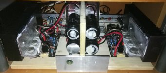
I want to share my recent rebuilding of my crescendo, with the TO3 FMmech boards. For the moment, all is mounted in a temporary wood board, but i'm in the way to choose a decent aluminium enclosure to finish this project. Absolutely no oscillations at any load, dead silent and well performing wiht my stereo set!!
I want to share my recent rebuilding of my crescendo, with the TO3 FMmech boards. For the moment, all is mounted in a temporary wood board, but i'm in the way to choose a decent aluminium enclosure to finish this project. Absolutely no oscillations at any load, dead silent and well performing wiht my stereo set!!
Attachments
Are you asking a question, or telling us a specification?You know that the original ELEKTOR PCBs had 70µm copper layer?
Best regards!
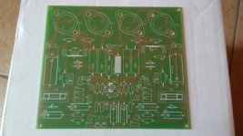
i read that the source resistor are the problem of oscillationIMHO The original PCB Layout of Crescendo is not so optimized, and prone to HF oscillations. Better employ a newer layout.

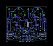
this is the original board .
something to improve?
the pcb is 146x129mm.
Hi scafas,
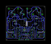
google for 'ray's audio page' and see, what can be improved.
Are you asking a question, or telling us a specification?
I know for sure that Elektor sold their PCB's for this project exactly with this specs.
Best regards!
i see , so i add some components on board to prevent oscillations..Hi scafas,
google for 'ray's audio page' and see, what can be improved.
Attachments
hello scafas,
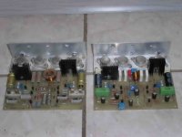
here is my modification done 2 years ago, according Rays page. Left side is the orignal , which was built 1985.
On the right side you see the modified board with Dale CMF 55 resistors and mica ,Panasonic FC, WIMA MKP and Frolyt bipolar capacitors. Also MJE350 and 340 as driver transistors and most important the source resistors as Metal Band resistor MPC 74, no wirewound resistors.
BR
Günni
Attachments
other mod on Rays page:hello scafas,
here is my modification done 2 years ago, according Rays page. Left side is the orignal , which was built 1985.
On the right side you see the modified board with Dale CMF 55 resistors and mica ,Panasonic FC, WIMA MKP and Frolyt bipolar capacitors. Also MJE350 and 340 as driver transistors and most important the source resistors as Metal Band resistor MPC 74, no wirewound resistors.
BR
Günni
- Use poor induction resistors for R27 to R30
- increases C16 from the Zobel network to 100nF and uses a MKP
- isolate T8 and T10 from the heat sink and connect them to zero
- Mount 22k load resistors for T8 and T10
- T8 and T10 may be needed. they are replaced by MJE340 and MJE350
- place a 100 nF capacitor on P1
- reduce the polystyrene from C2 to 100 pF
- Home
- More Vendors...
- Elektor
- Update for Elektor Crescendo Power Amplifier 1982