I have had 20 years and 3 months cressedno as the used preamp tube amplifier and the result was incredible and I found the atmosphere and warmth of the sound produced. Currently I'm stringing SK135 and J50 mosfet in the circuit that uses a buffer of LME 49830 from National Semiconductor, does anyone of you have tried it? and what were the results?
dear PMik, if you still have this article, please email me a copy to nkanil.klm@gmail.comWynand
Are you still interested to get the original article ?
I can send it for your email
Ps. I have today bought a "functional" Cresendo 180W for a symbolic amount of cash compared to the real cost of the parts/project, the owner informed me was not up to the task of getting the project finalized to perfection
The issues he had incounted was the ones bjornagain has posted the solution of in this tread ...
Thx bjornagain

(Late answer)Hey!
Make a crescendo amp.
Question: R23-24, R25-26 does not get put on the PCB?
THX!
Yes they are. Depending of the radiator you use, you can solder them track side of the Printed board.
Update and new build
Hi guys.
I am starting a new project based on Esperado's design: http://www.diyaudio.com/forums/elek...ndo-power-amplifier-1982-a-5.html#post2734507
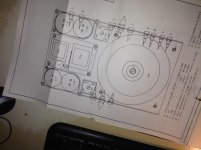
I am an electronics engineer and built the original (also created a whole made by hand plans and drawings, no computers for me in 85!) as a school project when I was studying, the job which was part digital electronics & part mechanical construction.
This amplifier is very good but very unstable as many of you have noticed/said.
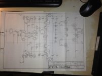
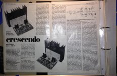
I also still got the original Elektor mag. featuring the Crescendo, in French, as you will see also on the pics.
I subsequently worked as a PCB designer ranging from PSU to RF devices in Switzerland and then the UK where I currently live.
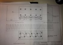
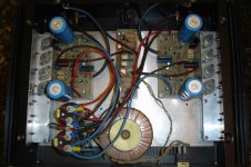
I am planning to redo a brand new PCB based on the original with Esperado's mods and re-use some of the original parts I still have (Huge toric transformer output 2x 75V and heat sinks with "L's" attached to it) all dressed into a very modern hand crafted case.
I have a fondness for this Amp as it was rated 7.5 out of 10 when compared to a 10/10 McIntosh amp tested on JM's speakers in a auditorium environment back in Switzerland where I used to live.
Given that the McIntosh was about $8000 I think that it is worth re-building one!
I measured an RMS output of 138W on one channel whereas the other threw 217W before clipping.
It also had a nasty bout of oscillation in the MHz's and this was more or less sorted by shielding/shorting the P fetmos TO3's cases with a piece of aluminium(!). But it fried a few T's in my time.
Well the new system will be designed with the experience I gained over the last 30years in the business (I since changed career, but it is like swimming, you never forget)
So I will try to post some updates from time to time, what I will also likely do is post on my blog: sxg.com | The personal site of Gilbert Serex – Linux enthusiast & Internet entrepreneur with a background in Electronic Engineering
which might move here: welcome to serex.me
Cheerio.
Hi guys.
I am starting a new project based on Esperado's design: http://www.diyaudio.com/forums/elek...ndo-power-amplifier-1982-a-5.html#post2734507
I am an electronics engineer and built the original (also created a whole made by hand plans and drawings, no computers for me in 85!) as a school project when I was studying, the job which was part digital electronics & part mechanical construction.
This amplifier is very good but very unstable as many of you have noticed/said.
I also still got the original Elektor mag. featuring the Crescendo, in French, as you will see also on the pics.
I subsequently worked as a PCB designer ranging from PSU to RF devices in Switzerland and then the UK where I currently live.
I am planning to redo a brand new PCB based on the original with Esperado's mods and re-use some of the original parts I still have (Huge toric transformer output 2x 75V and heat sinks with "L's" attached to it) all dressed into a very modern hand crafted case.
I have a fondness for this Amp as it was rated 7.5 out of 10 when compared to a 10/10 McIntosh amp tested on JM's speakers in a auditorium environment back in Switzerland where I used to live.
Given that the McIntosh was about $8000 I think that it is worth re-building one!
I measured an RMS output of 138W on one channel whereas the other threw 217W before clipping.
It also had a nasty bout of oscillation in the MHz's and this was more or less sorted by shielding/shorting the P fetmos TO3's cases with a piece of aluminium(!). But it fried a few T's in my time.
Well the new system will be designed with the experience I gained over the last 30years in the business (I since changed career, but it is like swimming, you never forget)
So I will try to post some updates from time to time, what I will also likely do is post on my blog: sxg.com | The personal site of Gilbert Serex – Linux enthusiast & Internet entrepreneur with a background in Electronic Engineering
which might move here: welcome to serex.me
Cheerio.
Attachments
Nice idea, but i still have few questions:I am starting a new project based on Esperado's design: http://www.diyaudio.com/forums/elek...ndo-power-amplifier-1982-a-5.html#post2734507
The power Fets used on this amplifier are no longer available. What is you position on this point ?
The original printed board was far to be optimal and participate to instability by their surface, tracks lengths and some other points. Did-you project to redesign-them from scratch ?
I believe we can improve this amp by adding a CCS to the input stage and add some cap multiplier to the input+VAS rails. What do-you think ?
They're available still... Not by Hitachi mind you.
2SJ50
2SK135
With regards to PCB, yes, I am going to redo the whole layout. Bit of trial and error but I think I might put the design on this Forum for scrutiny and then I can always rework it. I am using an open source program called Fritzing to do the PCB. looks good and they also provide etching service!
I'll keep you posted.
P.S. good to hear from you Esperado! I emailed you via your Form recently did you not get it? Might want to check your Form.
My question to you was about the image on your page which links to this image, I reckon your latter schematic is the right one, right?
Kay Pirinha
Sorry you don't read French it could be useful sometimes. Frankly I haven't really though about the ins and outs of Esperado's schematics, apart that any improvements is a good idea, removing the counter reaction circuit made of the BC546 and BC556 chain is definitely a good idea as they tended to go up in smoke in a wink whenever there were interferences.
I also did add some safety barriers in the original design at the time, like head butted Zeners between the input/ground to clip any massive glitches one can introduce when plugging or unplugging the audio cables. As one knows the Crescendo being such a sensitive and gigantic OP AMP was quite happy spewing whatever you fed it. Limiting the input is recommended.
2SJ50
2SK135
With regards to PCB, yes, I am going to redo the whole layout. Bit of trial and error but I think I might put the design on this Forum for scrutiny and then I can always rework it. I am using an open source program called Fritzing to do the PCB. looks good and they also provide etching service!
I'll keep you posted.
P.S. good to hear from you Esperado! I emailed you via your Form recently did you not get it? Might want to check your Form.
My question to you was about the image on your page which links to this image, I reckon your latter schematic is the right one, right?
Kay Pirinha
Sorry you don't read French
it could be useful sometimes. Frankly I haven't really though about the ins and outs of Esperado's schematics, apart that any improvements is a good idea, removing the counter reaction circuit made of the BC546 and BC556 chain is definitely a good idea as they tended to go up in smoke in a wink whenever there were interferences. I also did add some safety barriers in the original design at the time, like head butted Zeners between the input/ground to clip any massive glitches one can introduce when plugging or unplugging the audio cables. As one knows the Crescendo being such a sensitive and gigantic OP AMP was quite happy spewing whatever you fed it. Limiting the input is recommended.
Hi guys.
This amplifier is very good but very unstable as many of you have noticed/said.
It also had a nasty bout of oscillation in the MHz's and this was more or less sorted by shielding/shorting the P fetmos TO3's cases with a piece of aluminium(!). But it fried a few T's in my time.
Cheerio.
I have seen oscillation in a few amps including some of my early designs.
This is due to the signal getting to the output transistors before it gets to the return path in the LTP. The result is oscillation to some degree at the output.
I usually fix it with 100pf at the VAS stage across CB.
I recently updated and fixed a couple of Maplin 150WRMS amps that had the same problem. Fitting brand new transistors which were faster and had more gain set off oscillation. The 100pf trick fixed both of these too.
Never received your mail. Please, can-you copy-it in PM here ?I emailed you via your Form recently did you not get it? Might want to check your Form.
I usually fix it with 100pf at the VAS stage across CB.
Sorry, my Electronics background is French I am not familiar with these terms, can you explain between which connections you put the 100pf?
Would anyone else recommend it?
Thanks
discrepencies
Okay, just finished comparing the old design with the new one; little has changed, and Esperado, I am sorry to let you know that your PCB rewiring is incorrect Your PCB view connects the C19 and C20 capacitors (see schema below) on the other side of the R17 and R18.
Anyway the only unaccounted for elements that aren't on the original design are the ones circled in red below.
These two comps aren't present on the positive side.
Are these necessary just for the negative stage? or is that an error as I fail to understand what it does brings to this otherwise totally symmetrical schema
Thanks.
Okay, just finished comparing the old design with the new one; little has changed, and Esperado, I am sorry to let you know that your PCB rewiring is incorrect
Your PCB view connects the C19 and C20 capacitors (see schema below) on the other side of the R17 and R18.Anyway the only unaccounted for elements that aren't on the original design are the ones circled in red below.
These two comps aren't present on the positive side.
Are these necessary just for the negative stage? or is that an error as I fail to understand what it does brings to this otherwise totally symmetrical schema
Thanks.
Attachments
R17 and R18 was just a quick'n dirty little mod to adjust the DC offset 'on my amp'.Okay, just finished comparing the old design with the new one; little has changed, and Esperado, I am sorry to let you know that your PCB rewiring is incorrect
Anyway the only unaccounted for elements that aren't on the original design are the ones circled in red below.
These two comps aren't present on the positive side.
Are these necessary just for the negative stage? or is that an error as I fail to understand what it does brings to this otherwise totally symmetrical schema
Thanks.
Positive OR negative side, depending the sens of the offset.
We could do better adjusting the current sources via R6 or r29. Forget R39/C21.
Last edited:
Update, it's going to be a mixed SMD/THT PCB
Have been in contact with Esperado. Chatting away, in French, he mentions SMD on a layout. Well, it's my expertise, so I'll get most of the passive comps as SMD where possible. That's all the Resistors and some Condos.
I estimate this design will be over 50% smaller on the length.
I think double sided, that goes without saying.
Stay tuned for the initial schematic with all mods I think should be on.
Last edited:
 Guys
Guys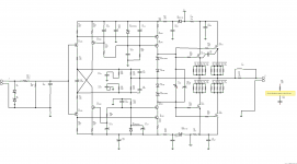
Hi trilbies,
It has been 2 years since I upgrade my original "Crescendos" as per Esperando's fine design.
I am very very please with the results ans still enjoy listening to them on a daily basis. I used a small piggy back board on top of the Elektor design. I believe the stability of the amp is related to the input capacitance of the outputs fets used. With the increased bandwidth this becomes even more critical. I did not try the capacitor across the sources as per Elektor's suggestion for inductive resistors but found that a 270pf capacitor and a 390R resistor in series from the collector of the BF470 driver and positive supply rail solved the problem. In addition, I injected a small amount of DC (high impedance) into the input to correct DC offset. I stuck with the fuses in the power rails to the output stage and increased the capacitor to 2,200uf after the fuses. I also put 22K resistors on the outputs of the voltage amplifiers as per the Millennium edition. My bias presets have a 100uf across them.
The polarity of your C29 in your diagram is backwards.
Sorry this is a bit long but hope it helps.
Best regards,
Paul
- Home
- More Vendors...
- Elektor
- Update for Elektor Crescendo Power Amplifier 1982