Thanks, very appreciated!
Which plastic FETs do you recommend to replace these 2SK135/2SJ50 originals?
Best regards!
Hi,
usually use 2SK1058 and 2SJ162 (End of life announced), but still available at the big R..... or the The Exicon ECX10P20/ECX10N20 still in production, see als thread group buy 2SK1058/2SJ162.
BR
Günni
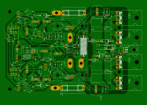
R31+C14 makes a very heavy load for the output.I would like to share some playworks. Close to original, but with additional places for plastic power transistor packages. Also places for compensation caps, as spice shows unconditional stability with few more pickofarads. All there in attachment, if some mistakes please write it here.
This amp is real legend, it deserves more buildings")
The Zobel is set to 10r+22nF and that extra loading is 1r+100nF
R31+C14 makes a very heavy load for the output.
The Zobel is set to 10r+22nF and that extra loading is 1r+100nF
It is only for spice analysing purpose. In praktice that conditions can occur only for short moment. This circuit shows no overshot on 20kHz square loaded by 100nF, and acceptable peak with 1uF, and without output coil.
By adding 2x 6.8 pF, 2x 10pF and decreasing four resistances this amp can simulate unconditional stability. Now it should be proved in practice.
@Kay
Why not revard Exicon for their work? Our friends already answered better than I could
Last edited:
Correction
sorry Kay
checking the layout, i found that the used output transistors have a BCE pinout (why bjt here?). the LATFets 2sk1058... and the Exicons have a GSD pinout (equivalent bjt BEC).
The used pinout is for Vert. Fets like IRFP 240/9240, and Toshiba 2SK1530/2SJ201. But they will not work in this board, since the temperature compensation for these types is missing here.
Gunni
Hi,
usually use 2SK1058 and 2SJ162 (End of life announced), but still available at the big R..... or the The Exicon ECX10P20/ECX10N20 still in production, see als thread group buy 2SK1058/2SJ162.
BR
Günni
sorry Kay
checking the layout, i found that the used output transistors have a BCE pinout (why bjt here?). the LATFets 2sk1058... and the Exicons have a GSD pinout (equivalent bjt BEC).
The used pinout is for Vert. Fets like IRFP 240/9240, and Toshiba 2SK1530/2SJ201. But they will not work in this board, since the temperature compensation for these types is missing here.
Gunni
Thanks for check. Forgrt bjt, it is here only to take measures.sorry Kay
checking the layout, i found that the used output transistors have a BCE pinout (why bjt here?). the LATFets 2sk1058... and the Exicons have a GSD pinout (equivalent bjt BEC).
The used pinout is for Vert. Fets like IRFP 240/9240, and Toshiba 2SK1530/2SJ201. But they will not work in this board, since the temperature compensation for these types is missing here.
Gunni
GSD variant in attachment
Attachments
if your 100nF across the output is intended to allow investigation of the phase margins of the amplifier, then it should be connected before the output inductor.It is only for spice analysing purpose. In praktice that conditions can occur only for short moment. This circuit shows no overshot on 20kHz square loaded by 100nF, and acceptable peak with 1uF, and without output coil.
By adding 2x 6.8 pF, 2x 10pF and decreasing four resistances this amp can simulate unconditional stability. Now it should be proved in practice.
@Kay
Why not revard Exicon for their work? Our friends already answered better than I could
Iductor is shorted, so in reality when inductor is applayed it will be more stabile. Also when testing squares input lp filter is removed.if your 100nF across the output is intended to allow investigation of the phase margins of the amplifier, then it should be connected before the output inductor.
But, as schillg11 said that VMOS is unusefull in this design, it push me into play Creshendo vith verticals. And, I am positively supprised with more accurate squares and lower distortion
- that combination is real beast. Something I wish to build, thanks schill.Crescendo_VMOS, with only small additional module for thermal control we have rock solid MOSFET amp.
All in attachment
Attachments
Last edited:
Iductor is shorted, so in reality when inductor is applayed it will be more stabile. Also when testing squares input lp filter is removed.
But, as schillg11 said that VMOS is unusefull in this design, it push me into play Creshendo vith verticals. And, I am positively supprised with more accurate squares and lower distortion
Crescendo_VMOS, with only small additional module for thermal control we have rock solid MOSFET amp.
All in attachment
Hi,
sounds interesting, but one remark for your VMOS version. The BD139 of your temperatuer compensation must be themally connected to the output stage, otherwise it will not work proper.
One further remark, for tuning the native Elektor Crescendo from 82 , just enter 'ray's audio page' in Google and you will get a lot helpful informations to update your existing Crescendo 82.
Based on these informations i think a new layout would be better using the parts that he suggested, for example the capacitors, the non inductive source resistors . If you use output transistors in plastic verison TO-264 or TO-247 . this layout can be shrinked by half. Also hard and expensive to get the TO-3 versions of these lateral Fets.
stay tuned and lots of success
Gunni
Yeah, almost haf.Hi,
sounds interesting, but one remark for your VMOS version. The BD139 of your temperatuer compensation must be themally connected to the output stage, otherwise it will not work proper.
One further remark, for tuning the native Elektor Crescendo from 82 , just enter 'ray's audio page' in Google and you will get a lot helpful informations to update your existing Crescendo 82.
Based on these informations i think a new layout would be better using the parts that he suggested, for example the capacitors, the non inductive source resistors . If you use output transistors in plastic verison TO-264 or TO-247 . this layout can be shrinked by half. Also hard and expensive to get the TO-3 versions of these lateral Fets.
stay tuned and lots of success
Gunni
Input transistors thermaly coupled due to lowered emiter resistances.
Bias current thermal control on board.
Almost half a size
If interest, I can upload gerbers.
Attachments
Looks fine, for such a short time!!
Can you please put the schematics also here?
two remarks so far,
a) please make it also possible to place metal band resistors (MPC71or BPR56) as source resistors (dot pitch 9mm) for prevent oscillation due to lower inductance
b) why not use a bipolar capacitor for C5 and C6 ( like Frolyt EKSU RM 5mm) ?
Nice work
Günni
So, heatsink ground as an option.
Optional 22k to collectors, for case if and when it is necessary.
Simulation shows unconditional stability without that resistors, but in reality never knows. Not to say that best sounding is not related to highest open loop gain
Optional 22k to collectors, for case if and when it is necessary.
Simulation shows unconditional stability without that resistors, but in reality never knows. Not to say that best sounding is not related to highest open loop gain
Attachments
Crescendo amplifier and HF
In the past , i studied and built many sort of V-Mos amplifier, so I know very well the original Crescendo and i have enjoyed a long time the mini-crescendo too. About high frequency, it is easy to find where to damp it it without altering the audio signal path.
Sorry for my bad English , i am French and i live near Paris.
Later i shall try to post a picture to show a good way you to cure HF issue.
How is it possible to send a picture in this forum?
In the past , i studied and built many sort of V-Mos amplifier, so I know very well the original Crescendo and i have enjoyed a long time the mini-crescendo too. About high frequency, it is easy to find where to damp it it without altering the audio signal path.Sorry for my bad English , i am French and i live near Paris.Later i shall try to post a picture to show a good way you to cure HF issue.
How is it possible to send a picture in this forum?- Home
- More Vendors...
- Elektor
- Update for Elektor Crescendo Power Amplifier 1982