Ulti Amp upgrade
Replacing the VAS transistors MJE15031 (T12) and MJE15030 (T13) with transistors 2SA1209 and 2SC2911.
To remain stability with Sanyo 2SA/SC transistors place a 47pF styroflex cap from base to collector for both semiconductors and replace the feedback 220pF cap Cfb for a 100pF styroflex or silvered mica cap.
Lower the idling VAS current to 12mA, by replacing the emitters resistors (R31…) . New resistor value 33 Ohms.
Lower the idling current in the second differential stage to 10mA, this comes down to 5mA per transistor leg.
Replace R51, 100E resistor by a 10E resistor and remove the short to power-ground.
Original matched dual transistors in this Elektor can be obtained (online) in Germany. Supplier is DSI who still offering the BFX36 and 2N914.
GES GmbH - www.Electronicpool.de - abgekündigte und schwer beschaffbare elektronische Bauteile
regards,
Piersma
GES GmbH - www.Electronicpool.de - abgekündigte und schwer beschaffbare elektronische Bauteile
regards,
Piersma
Hello "Piersma"
You seems to be the ULTI- specialist! Especially when I see how long you ingaged in this topic. I plan to start with this project in autumn this year. Before starting I would like to have solved all changes and improvements in the circuit and the bom.
At the moment I am just preparing a real pre-amp ( no caps in the signal line) with
proven design. If you are interested I would like to send you a pdf.-file for information. The only problem is, the paper`s language is german. I would be very pleased, if I could get any informations about your ULTI build phase. arothfr
Hi Piersma,
thank you very much for your quick reaction. Yes, I plan to build the ULTI-Amp!
When I read the ELECTOR pages, I decided for many years, this should be the right one. For the professional out looking, it shouuld fit into a YAMAHA- case of the M50 amp. My first steps will be to check are all part I need available, next must be what kind of issues are known. Here I would like to contact you; what experience did you
make, What are your next projects ? Regards : arothfr
Ulti Amp
Till this current day i still use the Ulti Amp as one of my preferred audio amplifiers. Ten years ago I a got a lot of emails from German builders who ran into trouble with this Elektor Amplifier, due to issues not mentioned (experienced) by Elektor. You should read this threat very carefully if you plan to build this "beast". You probably will run into problems sourcing the original parts by Elektor. Cross reference parts are still available.
Latest amplifier builds were Elvee's Circlophone and Roender's RFC-100.
Hello Piersma,
here some interesting information for your next project " the ULTI pre-amp".
Name and quality of sound fits together; this one is real professional!
Have a look at the circuit ( Done with LT1028AP, OPA 637BP,OPA 627BP ), open this link............, Regards arothfrhttp://www.huennebeck-online.de/dy/pre-1/pre-1.pdf
 This is an English language forum. Please post your replies in English.
Dear sir, if you have the article about this amp, please post it to forum or send it to me at nkanil.klm@gmail.com or at least the pcb layouts.Hi all,
Is anybody interested in almost all components and PCB boards for the ULTI-AMP as mentioned above.
It is available for anyone who is seriously interested in building his own audio power amp.
Best regards
Piersma
UltiAmp
Hi Piersma,
Looks like the ultiamp was very popular in the Netherlands!
I build 2 Monoblocks for 10 Years ago.
Audio Quality is very fine compared to more expensive commercial Amplifiers.
From the beginning I have some issues which I couldn´t solve and now I learned to live with:
1. The Heatsinks (where the 4 Sanken Transistors are mounted) gets extremely hot. I now use heatsinks twice the size and still need to use forced cooling so the Protection doesn't shut down every half an hour in summer.
2. The 6.3A fuses are destroyed approximately once every two months.
All voltages and currents seem to be in the appropriate range. Although the idle current in the Sanken Transistors is slowly fluctuating between min 165mA and max 200mA.
Do you have any suggestions/Ideas/Experience with these issues.
Thanks in advance,
JackV
hi Jack,
Over more than 10 years i have had a lot of (private)questions concerning this so called Ulti-Amp. All the builder ran into (serious) troubles, most of them are mentioned in this thread.
Temperature of the heatsink should be around 55 degrees (C)
What is your supply voltage and idle current?
When are the fuses blown? Powerup? It could be that the protection triacs are fired undeliberately. For a short time you might try it without.
I have had other Ulti Amps showing the same behaviour.
regards,
Piersma
Hi Piersma,
Thanx for your reply!
I was also starting to blame the Triac's. How could one solve this, are they necessary when you can shut down the Optocouplers?
Railvoltage is +/- 42V, idle current in Powerstage 165-200mA.
I was thinking about ocsillation but I can't see anything with a Scope.
How did you solve these issues?
My Ultiamp is build original, that means no upgrades (2N..., BFX... are installed) I had to adapt the feedback circuit (Both 1M resistors) to get the offset to 0V.
Maybe this could be the issue.
Regards,
JackV
Fuses blown
hi Jack,
You should check the output offset without the OP-77 DC servo, it should be in the range of serveral hundreds of millivolts or less. Extend the time to open de opto-couplers. This solved the problems in 2 Ulti Amp's which were brought in years ago.
regards,
Piersma
hi Jack,
You should check the output offset without the OP-77 DC servo, it should be in the range of serveral hundreds of millivolts or less. Extend the time to open de opto-couplers. This solved the problems in 2 Ulti Amp's which were brought in years ago.
regards,
Piersma
Hi Piersma,
Looks like the ultiamp was very popular in the Netherlands!
I build 2 Monoblocks for 10 Years ago.
Audio Quality is very fine compared to more expensive commercial Amplifiers.
From the beginning I have some issues which I couldn´t solve and now I learned to live with:
1. The Heatsinks (where the 4 Sanken Transistors are mounted) gets extremely hot. I now use heatsinks twice the size and still need to use forced cooling so the Protection doesn't shut down every half an hour in summer.
2. The 6.3A fuses are destroyed approximately once every two months.
All voltages and currents seem to be in the appropriate range. Although the idle current in the Sanken Transistors is slowly fluctuating between min 165mA and max 200mA.
Do you have any suggestions/Ideas/Experience with these issues.
Thanks in advance,
JackV
I found with class ab amps I didn't need very much bias current.
I got away with around 10mA and got no crossover distortion.
Sounded good too.
Measuring Session
Hi Piersma,
I will perform a measurement session to get some values including your suggestion of a decoupled OP77 (and also I think the LM337).
The only drawback here is finding time...")
By extending the optocoupler time you mean increasing the delay at which the optocouplers switch on during power-up (C3 / R4)?
I will post some results when I've performed the measurements.
I will also try to find out if the Triacs are activated shortly during Power-up. Maybe I will disable the Triacs completely (protection through optocouplers and Fuses).
@nigelwright7557: I believe the Ultiamp was originally designed with 200mA idle current through the SA/SC combination Class Ab
Regards,
JackV
Hi Piersma,
I will perform a measurement session to get some values including your suggestion of a decoupled OP77 (and also I think the LM337).
The only drawback here is finding time...
By extending the optocoupler time you mean increasing the delay at which the optocouplers switch on during power-up (C3 / R4)?
I will post some results when I've performed the measurements.
I will also try to find out if the Triacs are activated shortly during Power-up. Maybe I will disable the Triacs completely (protection through optocouplers and Fuses).
@nigelwright7557: I believe the Ultiamp was originally designed with 200mA idle current through the SA/SC combination Class Ab
Regards,
JackV
Measurements
It looks like the DC-setting is not correct.
The used LED's have a voltage of 1,7V, not all equal, therefor all currents in the Voltage amplifiers are too high. I will need to find LED's with specified 1,55V or change the resistors (R13, R14, R27).
Correction of DC offset is needed (already changed R74, R55) to succeed.
Also I found out that the currentsensing (Protection circuit 'A') is very sensitive. Measuring with a Multimeter resulted in two blown fuses (6,3A). For now i disconnected the Triacs.
maybe I could live without them!
Any suggestions?
Thanks!
- Home
- More Vendors...
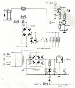
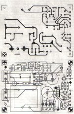
- Elektor
- Elektor's "Ulti Amp"